Welcome to Phoenix’s documentation!
Below is the latest documentation for CTR-Electronics Phoenix software framework. This includes…
Class library for Talon SRX, Talon FX, Victor SPX, CANCoder, CANifier and Pigeon-IMU (C++/Java/LabVIEW for FRC, C# for HERO)
Phoenix Tuner Graphical Interface - provides configuration options, diagnostics, control and plotting.
Phoenix Diagnostic Server - install on to roboRIO for Tuner, and to perform HTTP API requests for diagnostic information.
Blog Entries
Jan 08, 2021 - BLOG: FRC 2021 Kickoff
Feb 20, 2020 - BLOG: Falcon 500 / Talon FX Critical Update
Jan 04, 2020 - BLOG: FRC 2020 Kickoff
Mar 09, 2019 - BLOG: RoboRIO Performance Insight and Optional Phoenix 5.14.1 Update
Feb 16, 2019 - BLOG: FRC 2019 Week 6
Feb 01, 2019 - BLOG: FRC 2019 Week 4
Jan 11, 2019 - BLOG: FRC 2019 Week 1
Jan 04, 2019 - BLOG: FRC 2019 Kickoff
Dec 16, 2018 - Site Created
Follow these instructions in order!
FRC Blogs
BLOG: FRC 2021 Kickoff
Hello FRC Community!
We’ve just released our 2021 kickoff release of Phoenix Framework (5.19.4.1). The Phoenix Windows installer and zips for macOS and Linux are now available.
You can find the latest firmware CRFs at each product page (the installer also installs them).
The new features included in this season’s release are listed below.
Simulation Support
We’ve spent our offseason investing in a new suite of simulation features designed to allow effective development without requiring access to hardware.
This includes:
Simulation of device-level features, such as Motion Magic
Full feature support of Phoenix Tuner (including Plotter, Self Test Snapshot, Control, and Configs)
Support for simulated device-to-device features, such as follower mode and remote sensors/limit-switches
Integration with WPILib’s simulation GUI when using WPI_* classes
Supported Devices: Talon SRX, Victor SPX (future releases will include more devices)
Supported Operating Systems: Windows, Linux, macOS
Supported Languages: Java, C++
If you encounter any limitations with Talon SRX or Victor SPX simulation, please contact support@ctr-electronics.com or file an issue tracker here.
Phoenix Simulation Examples
For teams that want to start leveraging simulation features right now, the basic steps are:
Check out one of our examples that supports simulation (such as the Motion Magic example).
Open the example in Visual Studio Code and run in simulation.
Open Phoenix Tuner and set the Diagnostic Server Address to
localhost. Simulated devices will appear in Phoenix Tuner in a few seconds.Develop as normal.
Tip
We invite teams to leverage their preferred physics simulators by utilizing the SimCollection functions in Talon SRX and Victor SPX as seen here.
Note
Simulating non-FRC applications (not using WPI_* classes) will require calling Unmanaged.feedEnable(100); to enable simulated actuators.
Additional documentation for simulation will be available in the future.
Online API Documentation
The online API documentation has been updated for 2021.
C++ documentation can be found here.
Java documentation can be found here.
Java teams should note that the documentation jar is installed locally after running our installer.
LabVIEW
No new functionality has been added to Phoenix for LabVIEW users this season.
Release Testing Observations
During our release testing process, we observed the following limitations:
roboRIO 2021 v3.1 Image
We observed that we could not reliably image our roboRIOs with the 2021 v3.1 image. As a result, all of our testing has been done using the 2021 v3.0 image.
LabVIEW Deploy Limitation
We have noticed an intermittent issue that corrupts the Phoenix library files during LabVIEW deploy. This is reproduced by the following procedure:
Soft deploy your application (clicking the white arrow in Main.vi or <Ctrl>+R)
Hard deploy your application (right-click “FRC Robot Boot-up Deployment”, Run As Startup)
This dialog pops up when the issue occurs:
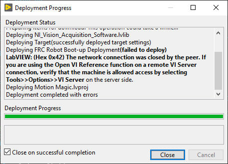
To solve this issue, hard deploy your application again.
Back-breaking API changes
In anticipation of future releases that support custom unit scaling, several of the Java and C++ routines have been updated to use doubles instead of ints.
We have also removed routines that have been deprecated for multiple seasons.
Removed motor controller routines:
set(ControlMode, double, double)
enableHeadingHold(bool)
selectDemandType(bool)
getActiveTrajectoryHeading()
Removed PigeonIMU routine:
configTemperatureCompensationEnable(bool, int)
Firmware
There are some new firmware files for this season. However, they are not required for general functionality.
A maintenance release (v21.0) for Falcon 500 (Talon FX), Talon SRX, and Victor SPX is available at each product page (the installer also installs them).
Good luck, and stay safe! - The CTRE Engineering Team
BLOG: Falcon 500 / Talon FX Critical Update
Hello FRC Community!
We’ve just released Phoenix API 5.18.2.1 to address a reported issue with Falcon 500 (Talon FX). This release requires the new Talon FX firmware (20.3.0.2). The Phoenix installer and non-Windows binary kit is now available.
You can also find the latest firmware CRFs at each product page (the installer also installs them).
New Talon FX Firmware 20.3.0.2
We received a small number of Falcon RMAs with a unique failure mode. After failure analysis, we found a circumstance where the tank capacitors inside the Talon FX can be damaged if certain conditions are met. The conditions require the following (for several seconds):
Disconnecting Falcon from battery (open breaker event or disconnect power harness from battery)
Back-driving the Falcon’s rotor above 3500 RPM (which will power up the electronics within the Falcon)
At least one of the following.
Commanding Falcon to drive motor while continuing to back drive Falcon above 3500 RPM.
Commanding neutral-brake while continuing to back drive Falcon above 3500 RPM.
These conditions can also be harmful with brushed motor controllers (3a in particular), but what makes Falcon unique is that:
it is a far more efficient generator than previous generation FRC controllers
condition 3.B. is unique to Falcon since it conditionally modulates neutral-brake during high-current events, which can exacerbate the issue.
The firmware update referenced above addresses this by detecting when these failure conditions occur). Motor output/brake will be disabled in this state, until the Falcon is properly powered again (breaker closes or supply brought back in circuit). When this occurs, Talon FX will blink a fault pattern (similar to thermal limit but green instead of orange).
Tip
You can still back-drive your robots when they are powered off (pushing an unpowered robot from one location to another is common). Manually back-driving does not reproduce this failure as this does not create enough energy, nor does it allow robot to be enabled for motor drive.
There will be two new faults to detect this condition:
Supply Unstable Voltage - reflects the motor controller’s inability to stabilize voltage due to the battery not being in circuit.
Supply Overvoltage - reflects the motor controller’s inability to prevent voltage from escalating well above the rated max voltage due to regenerative braking while battery is not in circuit.
Both are accessible via the fault API and Tuner Self-test Snapshot.
Note
Faults do not need to be cleared to resume normal functionality (faults are instrumentation only):
Warning
Because this firmware fix involves preventing a hardware damaging condition, the latest API release will require this version or newer to control Talon FX.
Falcon 500 Shaft Retention Screws
There have been recent reports of Falcons with insufficient Loctite on the shaft screws. VEX has released the following recommendation to apply Loctite to this seasons Falcons.
Warning
Note: We’ve found that some Falcons built during the first year (date code beginning in 19 or 200) may not have had Loctite properly applied to the shaft retaining screws. To be safe, we recommend that teams with first year motors open up them up and reapply Loctite 243 to all the shaft retention screws.
Documentation will be updated in various places to reflect this.
We strongly recommend teams inspect Falcons that are in use.
Future Firmware update - Talon FX / Falcon
We have one recent documented occurrence where if the Talon FX’s supply voltage drops to a narrow margin (4.6 - 4.8 V) and recovers, the Talon FX can be fooled into reporting a hardware fault (which causes a perpetual red/orange blink pattern).
This is not a typical voltage band to operate in. Talon FX has voltage monitoring features that prevent this in the majority of cases (even when using a depleted battery). However improper power wiring can cause this issue to occur (for example: Falcon red and black leads shorting to each other momentarily).
We’ve reproduced this and will have a firmware update coming to address it. It wasn’t released in time for today’s release, but should be out shortly.
EDIT: Fix is now available at https://github.com/CrossTheRoadElec/Phoenix-Releases/releases/tag/firm_FX_v20.4.1.0
BLOG: FRC 2020 Kickoff
Hello FRC Community!
We’ve just release our 2020 version of Phoenix API 5.17.3.1. The Phoenix installer and non-Windows binary kit is now available.
You can also find the latest firmware CRFs at each product page (the installer also installs them).
The new features included in this season’s release are listed below.
New Product - Talon FX
The biggest addition to the Phoenix software library is support for the new brushless integrated motor/motor-controller: The Talon FX (Falcon 500). Although this is a new product featuring several unique features, we developed the product in a way where the TalonSRX class can still be used to control the device. We believe this will allow teams to quickly integrate the new motor controller into their robots.
Additionally a new class called TalonFX has been added to the project. The API is very similar to the Talon SRX with the following differences:
TalonFX’s integrated sensor has a native resolution of 2048 units per rotation regardless of which class is used.
TalonFX’s default sensor type defaults to the integrated sensor (not quadrature).
TalonFX additionally supports TalonFXFeedbackDevice, to self-document the sensor types which are supported.
TalonFX additionally supports TalonFXControlMode (allowing future Talon FX specific control modes).
TalonFX allows simultaneous limiting of both stator (output) and supply (input) current.
New Product - CANCoder
The other major addition to our supported product list is CANCoder. The CANCoder is the next iteration of the popular CTRE Magnetic Encoder. Many aspects of the software was driven based on what we’ve learned in supporting the Mag Encoder.
Software features include:
The ability to choose how the Absolute Position is interpreted (±180 deg vs 360 deg).
The ability to manually offset the magnet position. This allows you to move inconvenient discontinuities outside of your mechanism’s operational range.
Simultaneous reporting of both the “relative” position and the “absolute position”. This means you can treat CANCoder as a relative sensor, then sync it again to become absolute.
Basic Phoenix Tuner features (device discovery, field-upgrade,id assignment, id conflict resolving, configs, etc.)
Customizable units string, coefficient, and time base (per second, per min) that work across Tuner and API.
Timestamped signal updates.
Support in all three FRC languages.
NI RoboRIO CAN Bus improvements
Some of you may have heard of the low level modifications done to the roboRIO CAN Bus software for 2020. This was to address some of the performance concerns brought on by teams in the previous season. For those not familiar, feel free to reference this blog entry discussing the performance limitations of the roboRIO when it comes to CAN bus.
Fortunately our friends at National Instruments have found a method to allow for faster calls to the CAN bus, allowing more CAN bus calls without slowing down your roboRIO loops. Even better, this was done in a way that doesn’t require fundamental changes to the higher level software leveraging CAN bus.
This means that this performance boost plus the buffering features of Phoenix allows for the best call performance for supported CAN bus peripherals to date.
However, as a result of these changes, the initial setup for Phoenix Tuner does change a bit. This is covered in detail below.
Phoenix Tuner 2020
In the past, users typically “install” our diagnostics software into the roboRIO in order to leverage Tuner features. As a result of the CAN changes, the diagnostic features have been moved into a library that is linked against the robot application. This means your Phoenix diagnostics will update any time you update the API.
However Tuner is typically used during hardware bring-up, long before any software is written. As such, Tuner is now capable of deploying a simple FRC application that will allow for Tuner use. Then once you’ve started deploying your own applications, Tuner will use the Phoenix libraries in your application to fulfill the same needs.
It’s a bit different than the previously season’s workflow, but we believe it will be worth the performance gains.
Online API Documentation
The online API documentation has not been updated yet, but it will be soon. Java teams should note that the documentation-jar is already installed locally after running our installer.
Back-breaking API changes
No back-breaking changes have been logged.
Good luck this build season! - Omar Zrien
BLOG: RoboRIO Performance Insight and Optional Phoenix 5.14.1 Update
Hello FRC Community!
There’s been several questions about the performance limitations of the roboRIO this season, particularly in regard to CAN-bus. In response to this, we’d like to provide some insight to better educate teams on the limitations of the control system. Additionally we made some tuning adjustments in Phoenix to help alleviate the symptoms caused by these limitations.
Please read the sections below for more information.
Omar Zrien Co-owner CTR-Electronics
roboRIO Limitations (“net comm”)
The roboRIO has a limitation where there is delay with every call that goes to the NI Network Communication process (often called “FRC NetComm”). This includes:
sending/receiving CAN
getting team/match info (see note below)
getting joystick data (see note below)
Generally anything involving the Driver Station software. (see note below)
Generally anything not from the FPGA.
Note
Most (but not all) of these are buffered in WPI C++/Java so they actually get called once every ~20 ms, regardless of how often you call getters. However the LabVIEW VIs appear to not be buffered and may experience this call delay.
These calls average approximately 0.3 milliseconds. Many of you may think that does not sound like much, but consider the number of get calls you execute on your peripheral devices per loop. Ten “get” calls on ten unique devices will yield 100 calls per loop, which would be 30ms (although Phoenix has optimizations to reduce this explained below).
The worst-case call time can also be much longer, several milliseconds in fact, depending on the task management of the operating system. We’ve found these worst-case events to occur intermittently and vary depending on:
CPU load
Ethernet traffic
Threading strategies
These intermittent call-delays can occasionally trip the WPILIB Driver Station warnings:
Watchdog not fed within 0.020000s (see warning below).
Loop time of 0.02s overrun.
Warning
This is not the same as the “Watchdog” issue that was addressed in roboRIO v14. That refers to the FPGA Watchdog, which is a component of the roboRIO, not WPILIB.
Which means you may be seeing these warnings despite having reliable control of the roboRIO during teleoperated operation. These intermittent events may also impact your robot negatively if you are using a software strategy that requires deterministic timing.
Phoenix 2017 - 2018 (last season)
In our library, there are typically three kinds of calls: getters, setters, and config routines.
Knowing that the average call time of the FRC/NI layer is 0.3 ms, we can predict the call time for the following scenarios:
~0.3 ms per call for any get* routines.
~0.3 ms per call for any set* or enable* routines where the input has changed since previous call.
~0 ms per call for any set* or enable* routines where the inputs have not changed since previous call
~4 ms for any successful config* routines if non zero timeoutMs is passed. These should be done on robot boot.
~X ms for any timed out config* routines if X timeoutMs is passed. These should be done on robot boot.
~0.3 ms for any config* if zero timeoutMs is passed. These should be done in the robot loop, if at all (generally not necessary). Success is not determined since there is no wait-for-response checking.
~4 ms for any successful configGet*. These are generally not necessary in a typical robot application.
Phoenix 2018 - 2019 (Kickoff release)
Over the summer of 2018, we added further optimizations to improve this. For example calling getSelectedSensorPosition() twice in your loop will not cost 0.6ms (2 X the average call time).
This is because Phoenix knows how often signals are updated, and can judge when it is appropriate to perform the call. We had beta teams test this and they reported improved performance.
Similarly if you call getters on signals from the same signal group only one of them will experience the 0.3 ms cost, and the rest will return the buffered data (at least until enough time has elapsed to justify checking the CAN-bus).
This reduces the actual calls into “FRC NetComm” considerably.
Phoenix 2018 - 2019 (New Optional Release v5.14.1.2)
For these optimizations to work reliably, we have thresholds to determine when to start checking the bus again for fresh data.
The kickoff release had conservative thresholds. This was appropriate given that the performance results were improved and this was a new feature for this season. However, given the number of teams reaching the limits of the roboRIO performance, we’ve released a new version with more aggressive thresholds (5.14.1).
To be clear, there are no API changes in this release. We would not feel comfortable making those types of changes during the competition season. This is merely an optional update for teams looking for any means of squeezing more performance out of their roboRIO + CAN bus peripherals.
As with any software component update, teams should re-validate all base functionality of their robot. If this cannot be done, then do not feel obligated to apply this update as this is entirely optional.
In general we recommend that teams attempting to use software loops for time critical tasks to:
Directly measure your “dT” (time between loop calls) and compensate for the measured deviations. WPILIB and LabVIEW provide routines to measure time.
LabVIEW teams can leverage the built-in profiler to profile their robot applications.
Consider updating to 5.14.1 if roboRIO limitations are impacting robot performance.
Review the number and type of “get” calls being done per loop. For example, if retrieving current-draw and sensor position, use getSelectedSensorPosition() instead of the routines in getSensorCollection(), since selected sensor position and current-draw are in the same status group.
Consider using the hardware-accelerated features of our motor controllers (Talon SRX, Victor SPX).
Note
There is a motor controller firmware update for teams using low-resolution sensors and Motion-Magic. However if you are using the feature successfully, you likely do not need to update.
Note
Some teams have opted to use alternative platforms that do not have the same call limitations. An example of this would be using Phoenix on Raspberry-Pi/Jetson TX2. These devices function by leveraging a kernel-based CAN-bus solution (socket-can).
How To download
Windows users can download the v5.14.1 Installer.
Alternatively, users can download the individual components:
Release page on GitHub: https://github.com/CrossTheRoadElec/Phoenix-Releases/releases
Firmware can be downloaded from the product pages on http://oldsite.ctr-electronics.com/
Additionally teams can pull the latest Phoenix API via the online method through VS Code, or via the non-Windows zip.
Download instructions can be found here.
Note
The online method refers to the “Check for updates (online)” feature. However this is not recommended as this requires a live Internet connection to use your FRC project.
BLOG: FRC 2019 Week 6
Hello FRC Community!
This weekend we have posted the Phoenix v5.14 feature release. This update has a few new Motion Control features we think will benefit teams as they wrap up their build seasons.
The features included are:
Talon and Victor firmware support for motion magic with S-Curve.
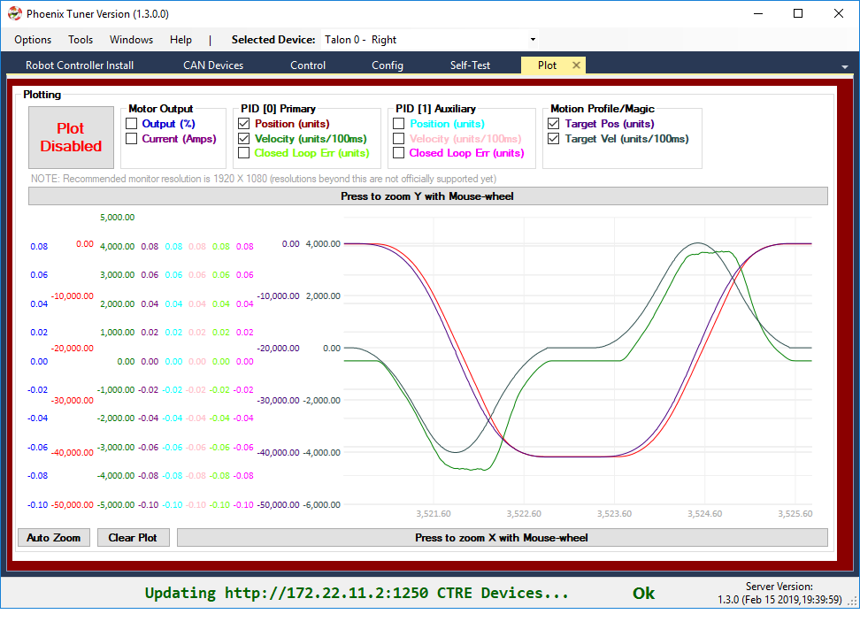
Tuner plotter can plot target position and velocity for MotionMagic/MotionProfile.
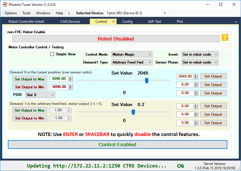
Tuner control tab supports testing several closed-loop modes including Motion Magic.
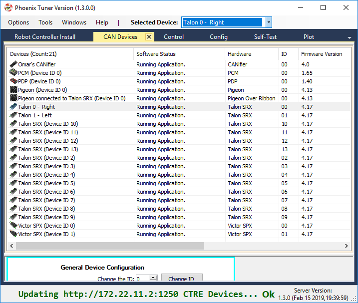
In this release the following components were updated:
New Tuner v1.3 (with Diagnostic Server v1.3)
New Phoenix API v15.4
New Firmware for Talon SRX (4.17) and Victor SPX (4.17)
Note
Latest Tuner and Diagnostic Server versions shown below (Tuner version in the top status bar, Server version in the bottom right - both report “1.3.0”).
The details of the update can be found in the release notes. See the sections below for more information and good luck this build season!
Omar Zrien Co-owner CTR-Electronics
New S-Curve feature
What is it?
The Talon SRX and Victor SPX Motion Magic control mode has definitely had a positive impact on FRC teams since its initial release in 2017. For the first time, teams could control their velocity profiles with virtually no additional software to develop. This feature works by using a strategy called Trapezoidal Motion Profile, a technique where constant acceleration is applied when adjusting the mechanism velocity.
However, trapezoidal profiling is not commonly used in industry. Instead, true motion profilers (CNC equipment for example) use S-Curve profiling. This means that the sharp “corner” points typical of the simpler trapezoidal method are smoothed to form a continuous curve.
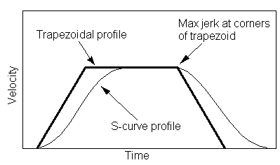
Note
Image source: http://www.ni.com/product-documentation/4824/en/
Due to the successful and widespread use of this control mode, we’ve enhanced it to allow for true S-Curve profiling.
Why use it?
Smoothing the profile generally leads to reduced oscillation in the movement caused by the “jerk” points that occur when the target velocity changes abruptly. This also means a more deliberate and reproducible maneuver, which is important in FRC.
As more teams become familiar with profiling techniques, classic trapezoidal profile may not be good enough for the future challenges team face.
How to use it?
C++ and Java teams will now be able to use configMotionSCurveStrength() to select how much smoothing to apply. This setting is available in the C++/Java API, as well as latest Tuner (config tab).
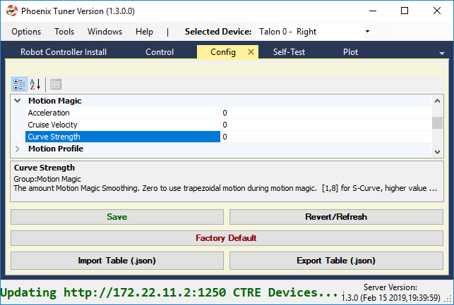
There are nine levels (0 through 8), where 0 represents no smoothing (same as classic trapezoidal profiling) and 8 represents max smoothing.
This setting also defaults to 0 to ensure a “smooth” transition when migrating from the older Phoenix releases.
New Tuner Plotter
Given the enhancement to Talon/Victor profiling, we also added the ability to plot the Motion Magic / Motion Profile target position and velocity. This will allow teams to learn about and tweak their profiles, as well as experiment with the new S-Curve feature.
Note
The capture below shows a “smoothed” MotionMagic velocity curve.
Note
The target velocity and position is also updated when using Motion Profile (streaming).
New Tuner Control
The Tuner control tab now provides the means of testing:
Percent Output
Position Closed-Loop
Velocity Closed-Loop
Motion Magic Closed-Loop
Current (draw) Closed-Loop
The graphical interface has been enhanced a bit to cover the various combinations of control strategies. For teams who leverage advanced features (such as arbitrary feed-forward or auxiliary PID1), uncheck the “Simple View” checkbox to get all the bells and whistles.
How To download
Windows users can download the v5.14 Installer, which provides all three components.
Alternatively, users can download the individual components:
Release page on GitHub: https://github.com/CrossTheRoadElec/Phoenix-Releases/releases
Firmware can be downloaded from the product pages on http://oldsite.ctr-electronics.com/
Additionally teams can pull the latest Phoenix API via the online method through VS Code, or via the non-Windows zip.
Download instructions can be found here.
Note
The online method refers to the “Check for updates (online)” feature. However this is not recommended as this requires a live Internet connection to use your FRC project.
BLOG: FRC 2019 Week 4
Hello FRC Community!
This week we are releasing our first comprehensive update for the 2019 season. Our test plan for this release was vigorous and took longer than we expected to complete, but we are satisfied with the results.
In this release the following components were updated:
New Tuner v1.2 (with Diagnostic Server v1.1)
New Phoenix API v15.3
New Firmware for Talon SRX (4.15), Victor SPX (4.15) and Pigeon IMU (4.13).
A breakdown of the changes are below, but due to the variety of improvements and how these components interact, we strongly recommend collectively updating all three components before Stop Build Day.
How To download
Windows users can download the v5.13 Installer, which provides all three components.
Alternatively, users can download the individual components:
Release page on GitHub: https://github.com/CrossTheRoadElec/Phoenix-Releases/releases
Firmware can be downloaded from the product pages on http://oldsite.ctr-electronics.com/
Additionally teams can pull the latest Phoenix API via the online method through VS Code, or via the non-Windows zip.
Download instructions can be found here https://phoenix-documentation.readthedocs.io/en/latest/ch05_PrepWorkstation.html#what-to-download-and-why
Note
The online method refers to the “Check for updates (online)” feature. However this is not recommended as this requires a live Internet connection to use your FRC project.
See the sections below for more information and good luck this build season!
Omar Zrien Co-owner CTR-Electronics
New Tuner v1.2 (with Diagnostic Server v1.1)
Comms Improvements
The biggest update to the Phoenix Tuner/Diagnostic Server package is updating the communication method to use the latest Windows web-request API. This appears to have solved the remaining customer reports where the browser responds correctly to Diagnostic Server, but Tuner does not.
Memory and performance improvements were also made to improve the runtime behavior when leaving the software connected for extended periods of time.
If you experienced any communication issues with the Kickoff release of Tuner, we strongly recommend switching to the latest Tuner and installing the latest Diagnostics Server (Robot Controller Install tab).
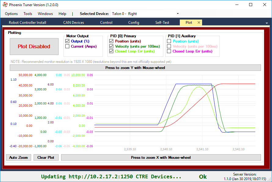
Plotter Improvements
Some teams are beginning to move into the “tuning” phase of their mechanisms, so we added a few more channels to the plotter.
Phoenix Libraries cleared on roboRIO reboot
We received a couple reports where the roboRIO appears to be losing Phoenix libraries after a power cycle. The root-cause was determined to be teams accidently using HERO LifeBoat to install 2018 libraries in a location that prevents the 2019 libraries from loading correctly. Details on this can be found at https://github.com/CrossTheRoadElec/Phoenix-Releases/issues/1
To solve this completely we made two changes:
Latest Phoenix Tuner will find and delete the erroneously placed 2018 library files.
Latest HERO LifeBoat will not install libraries into a roboRIO.
If this applies to your robot, we recommend downloading latest Tuner (via Windows Installer or via GitHub releases) and perform a fresh “Robot Controller Install” to ensure no loss of functionality after RIO reboot.
Misc Updates
We’ve also made several minor corrections to the Self-test Snapshot results, and compatibility adjustments to match latest firmware. The details can be found in the release notes.
New Phoenix API v15.3
Desktop Simulation - Our first steps
Teams using VS Code may have noticed a checkbox in the “Create New Project” prompt for “Desktop Support”. When checked, the newly created project is setup to perform desktop compilation in addition to compiling for the roboRIO. This can provide the means of testing newly written code when you are away from the roboRIO.
In the previous 2019 release of Phoenix, the desktop libraries required for this feature were not packaged. But that has changed - starting with v5.13, you can now set this checkbox, thereby enabling the desktop builds to compile on your native machine. This means your roboRIO project that links Phoenix will now compile on Windows/Linux desktop.
Note
This may slow the build time of your source due to the additional compile tasks.
Although the project will compile, you will notice the typical Driver Station errors when communicating with CTRE Devices that are not present on the CAN bus. This is why we consider this our “first step” in simulation. Future releases will include more comprehensive support, with the ultimate goal of full-simulation of our CAN devices.
Jetson TX and Raspberry Pi
The classifiers for our armhf and aarch64 builds have been modified to explicitly name the Jetson TX2 and Raspbian toolchain. This better communicates the intended target platforms of these libraries, and aligns the Raspbian binary artifacts with WPILIB’s naming scheme.
Pigeon Pitch/Roll
A couple teams reported that the API to poll Pitch and Roll were not correct if the angle is steep enough. This has also been solved in this release.
New Firmware - Talon SRX (4.15), Victor SPX (4.15) and Pigeon IMU (4.13)
Pigeon IMU (4.13)
This hot-fix was released over two weeks ago to solve an issue for teams using the remote-sensor/Arc features of the Talon SRX.
https://github.com/CrossTheRoadElec/Phoenix-Releases/releases/tag/Pigeon_IMU_v4.13
Since this is the first installer since the hot-fix, this CRF has been included.
Talon SRX / Victor SPX Firmware (4.15)
A critical fix has been applied to the Talon SRX and Victor SPX firmware for those of you using the firmware closed-loop features. We’ve identified a circumstance where measurement noise can occur in the sensor velocity and closed-loop derivative error, when motor output is less-than-full, and the current-draw measurement is nonzero and changing.
This was first discovered and reproduced by FRC Team 2767 Strike Force. If that name sounds familiar, you’ve probably watched an FRC World Championship, or two.
Thanks to the feedback from 2767, we’ve solved the issue with several performance improving fixes. The issue was root-caused to be an inefficiency in the current-draw calculation, which has been addressed in 4.15. Note that the current-measurement in 4.15 may report slightly different values when compared to previous firmware (within 0.100A) due to rounding changes.
Because measurement noise can be very difficult to diagnose, we strongly recommend teams using the closed-loop features of Talon to update. If you are using the closed-loop features successfully, you may find that updating will improve your tuning experiences (gains seem to be easier to find).
Additional firmware updates
The additional firmware changes are also mentioned in the release notes.
BLOG: FRC 2019 Week 1
Hello FRC Community,
It’s the end of “week 1” of the build season, and a good time for an update from CTRE.
C++/Java teams appear to generally be successful becoming familiar with this year’s new software collection (VS Code + Phoenix + Tuner). If your team has not updated yet, we recommend starting with WPI Screensteps, then running through Phoenix Framework Documentation for CTRE devices.
LabVIEW teams appear to be up and running as well with our kickoff software library. We’ve encountered a single report of an install related issue, which has been reproduced and fixed. As a reminder to teams, please use Tuner to install the Phoenix library into your roboRIO, and not last year’s HERO LifeBoat.
See the sections below for more information and good luck this build season!
Omar Zrien
Co-owner CTR-Electronics
Updated API Docs
This week we went through our C++/Java API filling in any missing comment block sections. The online API doc has been updated for C++ and Java. Of course if you still have questions, feel free to contact our support directly.
Remember to update the firmware!
We got a few support calls/emails this week from teams reporting that their Talon SRX motor controllers would not enable as expected. Here were the root-causes we found:
Wrong firmware - Didn’t update.
Still wrong firmware, where is the web-dash? What’s Phoenix Tuner?
Didn’t set device IDs.
We are supposed to use VS Code now? When did that happen?
No we didn’t install anything called Phoenix. What’s that?
But more often than not, the root-cause was not updating to this year’s firmware (4.11). Once updated, teams were ready to rock and roll.
So as a reminder, teams should ensure that their motor controllers are up to date for proper functionality with 2019 software.
Phoenix on other platforms?
Some teams are already aware that Phoenix isn’t just a library targeted for the roboRIO. For those of you perusing our maven site you may have noticed several Linux binaries. These have been used for leveraging Talons/Victors/CANifiers/Pigeon on third party hardware such as:
Raspberry PI + SocketCAN interface
NVIDIA Jetson TX2 + native CAN
Even Linux Desktop with SocketCAN device plugged in.
After reviewing the FRC rules, it appears that leveraging these CAN devices from third-party CAN hardware is now officially FRC legal. This opens up an entirely new way to develop robots in FRC.
Want to update your set-points from your Raspberry PI vision system?
Want to run closed-loops in your NVIDIA Jetson?
Do you prefer a development platform/environment outside of the roboRIO control system?
For the first time ever, you can now update your control outputs outside of the roboRIO, while the roboRIO safely manages the enable/disable of your Talon SRXs and Victor SPXs.
The requirements for this are to link the appropriate Phoenix-targeted library into your application (typically Linux-amd64, Linux-armhf, Linux-aarch64), allowing you to use the same Phoenix API on your platform.
Additionally you must provide a CAN bus interface. A popular method to do this is with through SocketCAN.
And finally make sure Phoenix loads on the roboRIO, either by creating a dummy Phoenix CAN device that is not on the bus, or calling the new loadPhoenix() routine.
We have a GitHub example demonstrating this type of control on an FRC robot with a Raspberry PI + CANable(USB). Driver station is used to enable/disable the robot, and the rest is done in the Raspberry PI C++ application.
Note
Reading gamepads inputs on a raspberry pi is typically not FRC legal, but controlling the Talons from the pi now is.
Note
This applies to CAN-bus control of Talon SRX/Victor SPX, and not PWM.
Phoenix Tuner 1.0.2
We released a minor update to Tuner today. Tuner 1.0.2 is packaged with today’s installer (see below) but also available as a separate download…
https://github.com/CrossTheRoadElec/Phoenix-Releases/releases
Fixes:
Improved the form response to high-dpi monitors. Note that the plotter features still work best at 1920 X 1080 (otherwise Windows may auto-scale the application on plotter-enable).
Improved mDNS resolving. This improves discovery of the roboRIO when user enters team number instead of a static-IP or 172.22.11.2 (USB) host name.
Phoenix Framework 5.12.1
We also released a minor Phoenix update today.
https://github.com/CrossTheRoadElec/Phoenix-Releases/releases
The same API comment-block updates that were applied on our site are now in our library so that VS Code Intellisense can display more information.
Tip
C++ teams may have to invoke “./gradlew clean” and/or “WPILib C++: Refresh C++ Intellisense” for Intellisense to update.
Our maven site has also been updated with the 5.12.1 libraries.
We also added more firmware version checking (we report a DriverStation message already, but we now do it as soon as the Phoenix object is created, instead of waiting for you to call certain routines). We were motivated to do this due to the support calls we got this week mentioned earlier :)
And finally we fixed the context help for SetInverted.vi (LabVIEW), this was reported by a team.
This minor update also provides an opportunity for C++/Java teams to become familiar with the “Update” instructions for third-party libraries. Be sure to review the update instructions
Balance Bot
Last year during the Worlds Championships, we demoed a small 2-wheeled balance bot using our HERO control system. No, I don’t expect any competition robots to employ the same drive train :)
But during the off-season, we redesigned it to be easier to 3D print, assemble, and support. Earlier this week we were asked about the demo, only to realize we never posted the files!
The CAD and source is now available on GitHub.
BLOG: FRC 2019 Kickoff
Once again it is time to kick off a new FRC season!
The Phoenix installer and non-Windows binary kit is now available.
You can also find the latest firmware CRFs at each product page (the installer also installs them).
The new features included in this season’s release are listed below. What’s great about this list is that every single feature was a request from an FRC student or mentor. Also this year’s API release is almost entirely backwards compatible.
New features below
Motor controller followers can use SetInverted(enum) to match or oppose master motor controller. SetInverted(bool) still exists and works exactly the same as last season.
Motion Profile and Motion Profile Arc have an explicit feedforward term (allows for kS, kV, kA, etc..) for both primary and aux PIDs.
Motion Profile (and Arc) use a linear interpolator to adjust the targets every 1ms. This means you can send less points, reducing CAN bandwidth, but still have resolute control.
Motion Profile API has a simpler mode where you can simply call Start/IsFinished. Legacy API still exists and is supported.
Phoenix Tuner and Phoenix Diagnostics Server replaces the silverlight based diagnostics from past seasons.
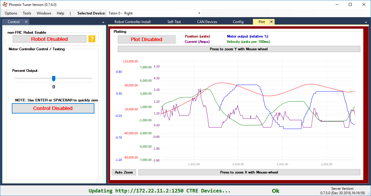
Phoenix Tuner provides the means of controlling Talons for simple testing.
Phoenix Tuner includes a plotter.
Phoenix Tuner provides import and export of all config settings.
Phoenix Tuner can be used to factory default config settings (as well as API).
Phoenix Tuner can field-upgrade all same-model devices with one click.
Phoenix Tuner can be used to perform Pigeon IMU temperature calibration.
New config routines to simplify management of persistent settings: configFactoryDefault and configAllSettings
Compatibility with WPI distributed Visual Studio Code interface and GradleRIO build system.
Maven hosted API provides an alternative to using the Phoenix installer to get API binaries (however the offline install is highly recommended).
No more FRC versus nonFRC firmware, see “FRC Lock” features for explanation.
Phoenix C++ API is portable to RaspPI, Linux-Desktop, NVIDIA Jetson TX2, etc.
Performance improvements of general status CAN get routines (get routines take far less time to execute than previous seasons).
Talon SRX: Maximum reportable velocity increased. New maximum RPM is 38400 RPM (@ 4096 untis per rotation).
C++/Java: Added default parameter values for pidIdx, slotIdx, and timeoutMs where appropriate.
Note
Installing Phoenix on another Linux device and controlling Talon SRX / Victor SPXs may or may not be FRC legal depending on 2019 rules.
Fixes
Current Limit Errata fixed from last year on Talon SRX.
SetYaw fixed from last year to be in degrees on Pigeon IMU.
Back-breaking API changes
If using Motion Profile Arc, be sure to set the bAuxPID flag to true in the trajectory points. This member variable did not exist before.
Motion Profile Trajectory point duration is now integer (milliseconds) with [0,127] ms range.
MotionMagicArc enum removed from LabVIEW. This enum was never used. Arc’ing with Motion Magic is accomplished with the four-parameter set() and MotionMagic enum.
Good luck this build season! - Omar Zrien
Phoenix Software Reference Manual
This is the latest documentation for CTR-Electronics Phoenix software framework. This includes:
Class library for Talon SRX, Victor SPX, CANifier and Pigeon IMU (C++/Java/LabVIEW for FRC, C# for HERO).
Phoenix Tuner GUI - provides configuration options, diagnostics, control and plotting.
Phoenix Diagnostic Server - install on to RIO for Tuner, and to perform HTTP API requests for diagnostic information.
Be sure to follow the following instructions in order to ensure success in developing your robot platform.
Primer: CTRE CAN Devices
CTR-Electronics has designed many of the available CAN bus devices for FRC-style robotics. This includes:
Talon FX, Talon SRX, and Victor SPX motor controllers (PWM and CAN)
CANCoder
Pigeon IMU
CANifier
Pneumatics Control Mode (PCM)
Power Distribution Panel (PDP)
These devices have similar functional requirements, specifically every device of a given model group requires a unique device ID for typical FRC use (settings, control and status). The device ID is usually expressed as a number between ‘0’ and ‘62’, allowing use for up to 63 Talon SRXs, 63 Victors, 63 PDPs, etc. at once. This range does not intercept with device IDs of other CAN device types. For example, there is no harm in having a Pneumatics Control Module (PCM) and a Talon SRX both with device ID ‘0’. However, having two Talon SRXs with device ID ‘0’ will be problematic.
These devices are field upgradable, and the firmware shipped with your devices will predate the “latest and greatest” tested firmware intended for use with the latest API release. Firmware update can be done easily using Phoenix Tuner.
The Talon FX/SRX and Victor SPX provide two pairs of twisted CANH (yellow) and CANL (green) allowing for daisy chaining. Other devices such as the PDP and PCM have Weidmuller connectors that accept twisted pair cabling. Often you will be able to use your Talons and Victors to connect together your PCM and PDP to each other.
The CAN termination resistors are built into the FRC robot controller (roboRIO) and in the Power Distribution Panel (PDP) assuming the PDP’s termination jumper is in the ON position.
More information on wiring and hardware requirements can be found in the user manual of each device type.
Primer: What is Phoenix Software
Phoenix is a package that targets LabVIEW, C++, and Java for the FRC Robotics Controller platform, i.e. the NI roboRIO robot controller.
It includes the Application Programming Interface (API), which are the functions you call to manipulate the CTRE CAN bus devices: Talon FX, Talon SRX, Victor SPX, CANCoder, CANifier, and Pigeon IMU.
Note
PCM and PDP API are built into the core WPI distribution.
The C++ and Java APIs are very similar, typically only differing on the function name case (configAllSettings in Java versus ConfigAllSettings in C++). Because Java is more widely used in FRC than C++, this document will reference the Java routine names. C++ users should take note that the leading character of every function is UPPERCASE in C++.
Additionally, Phoenix shared libraries are also targeted for C++ on Linux (amd64, armhf, aarch64) and typically available on our maven repository. The example support libraries use socket-can for CANBus access, however custom drivers can be provided by the end user for alternative CANBus solutions (NVIDIA TX2 native CAN bus for example).
Phoenix also includes a NETMF (C#) class library for the non-FRC HERO Robot Controller. This can replace the roboRIO in use cases that don’t require the full features of the FRC control system, and are not in use during competition.
Note
With Phoenix framework, teams can control/leverage Talons, Victors, Pigeons, CANCoders, CANifiers outside of the roboRIO (e.g. Rasp-Pi or Jetson TX2), and use the roboRIO/DriverStation to safely enable/disable the actuators.
Note
Leveraging CTRE CAN devices from third-party CAN hardware was officially made FRC legal for the 2019 season.
There are tons of examples in all languages at CTRE’s GitHub account:
https://github.com/CrossTheRoadElec/Phoenix-Examples-Languages
https://github.com/CrossTheRoadElec/Phoenix-Examples-LabVIEW
Entire GitHub organization: https://github.com/CrossTheRoadElec/
Phoenix-Examples-Languages and Phoenix-Examples-LabVIEW are specifically tested on the FRC RoboRIO control system.
Phoenix-Linux-SocketCAN-Example demonstrates control of Talons from a Raspberry Pi. https://github.com/CrossTheRoadElec/Phoenix-Linux-SocketCAN-Example
What is Phoenix Tuner?
Phoenix-Tuner is the graphical interface that allows for configuration of Phoenix CAN bus devices.

It provides a variety of functionality to support all Phoenix CAN Bus devices. The feature set includes:
Update device firmware (including PDP/PCM)
Change CAN IDs
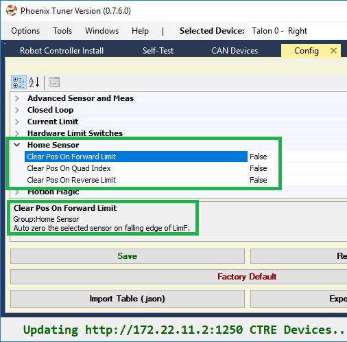
Configure direction and offsets
Self-test Snapshot devices
Change configuration settings
Factory default configuration settings
Test motors
Check plots
Temperature Calibrate Pigeon-IMU
Confirm proper CAN bus wiring without writing any software.
Now you can drive your motors and collect data without writing any software.
Configuration values can be checked, modified, and defaulted with the new config view. Config values can also be imported/exported as an easy-to-follow JSON formatted file.
The following sections of documentation will cover how to use Phoenix Tuner and the other components of Phoenix.
Tip
Have a feature request? Send to us at support@ctr-electronics.com or report it on GitHub.
Do I need to install any of this?
Yes, if any of the following:
You need library support for Talon SRX, Talon FX, Victor SPX, CANCoder, CANifier, Pigeon IMU
You need to field upgrade Talon SRX, Talon FX, Victor SPX, CANCoder, CANifier, Pigeon IMU, PDP, or PCM
You want to use Phoenix Tuner for CAN diagnostics (highly recommended)
Note
PCM and PDP objects are already supported in the base FRC installation. However, Phoenix Tuner is required for setting the device ID, field-upgrade, and Self-test Snapshot.
Prepare your workstation computer
Before Installing Phoenix…
It is strongly recommended to complete the base installation of FRC tools. https://docs.wpilib.org/en/latest/docs/getting-started/getting-started-frc-control-system/control-system-software.html
Warning
You will need to image the roboRIO to 2020 software before continuing. The roboRIO kickoff versions are image 2020_v10.
Test base FRC Installation - FRC LabVIEW
If a team intends to use LabVIEW to develop robot software, be sure to complete the full NI installer. At which point, opening LabVIEW should reveal the FRC-styled graphical start menu.
At this point it is recommended to create a simple template project and test deploy to the roboRIO. Be sure the DriverStation can communicate with the robot controller, and that DS message log is functional.
Note
LabVIEW is versioned 2019 due to its release schedule. Therefore, LV2019 is used for the 2020 season.
Test base FRC Installation - FRC C++ / Java
It is recommended to install the FRC Driver Station Utilities. This will install the Driver Station software, which is necessary for:
Basic comms checks
Reading joystick data
Generally required for enabling motor actuation (Phoenix Tuner Control features may require this, depending on setup).
General Recommendations for FRC C++ / Java.
The FRC C++/Java standard distribution for 2020 is based on the Microsoft Visual Studio Code development environment with WPI extensions.
If you are not familiar with developing C++/Java FRC programs, we strongly recommend testing full deployment to your robot controller before installing Phoenix and porting previous season software. A recommended test is to:
Create a project from scratch
Make a simple change such as add a print statement with a counter.
Deploy (or debug) your application.
Confirm robot can be teleop-enabled in DS.
Open FRC message Console and read through all the messages.
Repeat 2 - 5 ten times. This will train students to become familiar with and build general confidence in the tools.
Note
Third-party vendor libraries are installed into the C++/Java project, not the environment. For each C++/Java project you create, you must use the WPI provided tools to select Phoenix to bring the libraries into your project.
What to Download (and why)
Option 1: Windows installer (strongly recommended)
Environments: Windows-LabVIEW, Windows-C++/Java, HERO C#
Phoenix Installer zip can be downloaded at:
https://store.ctr-electronics.com/software/.
It is typically named Phoenix Framework_Windows_vW.X.Y.Z.zip
This will install:
The LabVIEW Phoenix API (if LabVIEW is detected and selected in installer)
The C++/Java Phoenix API (if selected in installer)
Device Firmware Files (that were tested with the release)
CTRE Support of RobotBuilder
Phoenix Tuner
Installs Phoenix API libraries into the roboRIO (required for LabVIEW)
Installs Phoenix Diagnostics Server into the RoboRIO (needed for CAN diagnostics).
Plotter/Control features
Self-test Snapshot
Device ID and field-upgrade
Option 2: Phoenix API via Non-Windows Zip
Environments: Linux/MacOS - C++/Java
The Phoenix API can be manually installed on non-Windows platforms by downloading the “non-Windows” zip and following the instructions found inside.
This essentially contains a maven-style repository that holds the API binaries and headers, as well as a “vendordeps” JSON file that instructs VS how to incorporate the Phoenix C++/Java API libraries.
Note
This is auto installed when using the Windows full installer (Option 1).
Phoenix Tuner
Environments: Windows
If you are using option 2, you will need to download Phoenix Tuner separately. Phoenix Tuner is available here… https://github.com/CrossTheRoadElec/Phoenix-Tuner-Release/releases
This can be convenient for workstations that aren’t used for software development, but are used for field-upgrade or testing motor controllers.
Note
LabVIEW teams may need to use Phoenix Tuner to install Phoenix libraries into the roboRIO. More information on this can be found under Prepare Robot Controller.
Note
This is auto installed when using the Windows full installer.
Note
Developers may be interested to know that all Phoenix Tuner features leverage an HTTP API provided by the Phoenix Diagnostics Server. As such, custom tooling can be developed to field-upgrade, test-control, or diagnostics CTRE devices without Tuner.
Device Firmware Files (crf)
The test firmware files for all CTRE devices are packaged with the Windows Installer (and has been for years). However, many FRC teams don’t notice, or prefer to download them directly from the product pages on the ctr-electronics.com website. If Internet access is available, they can be downloaded as such.
The FRC Software installer will create a directory with various firmware files/tools for many control system components. Typically, the path is:
C:\Users\Public\Documents\FRC
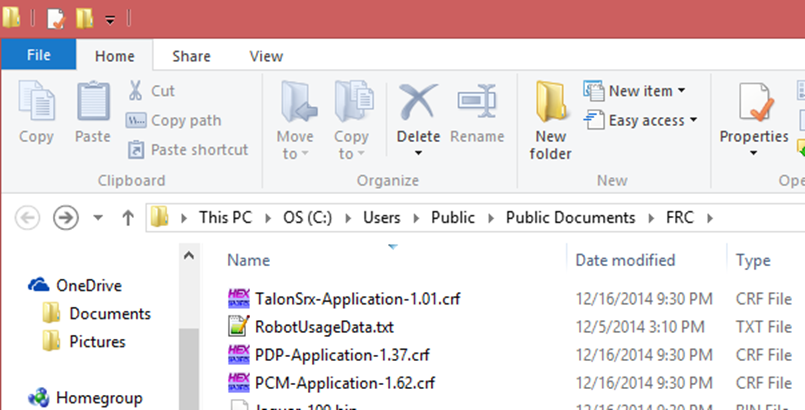
When the path is entered into a browser, the browser may fix-up the path:
C:\Users\Public\Public Documents\FRC
In this directory are the initial release firmware CRF files for all CTRE CAN bus devices, including the new Talon FX and CANCoder.
The latest firmware to be used can be found in the Software Release Notes.
Note
Additionally, newer updates may be provided online at https://store.ctr-electronics.com/software/.
Note
There is no longer FRC versus non-FRC firmware for motor controllers. Instead the latest firmware detects if the use case is FRC. If so, the device will FRC-Lock, and will require the Driver Station for actuation.
Workstation Installation
There are three installation methods listed below. The simplest and recommended approach is to run the Windows Installer (Option 1).
Option 1: Windows Offline Installer (C++/Java/LabVIEW, HERO C#)
Un-compress the downloaded zip.
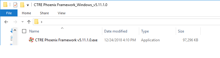
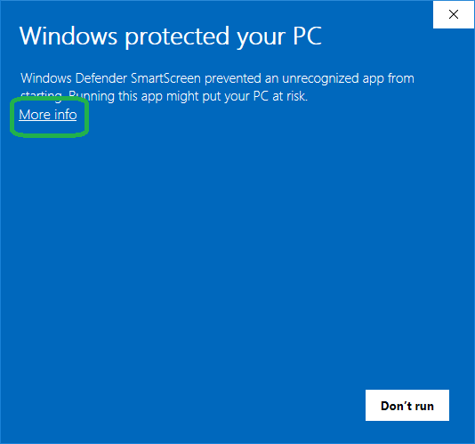
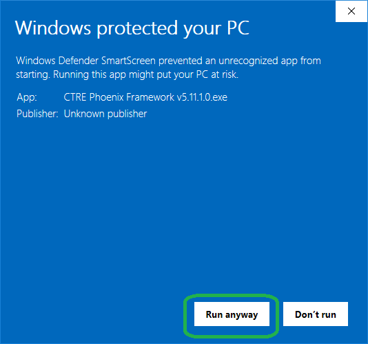
Double click on the installer. If the Windows protection popup appears press More Info, then Run anyway.

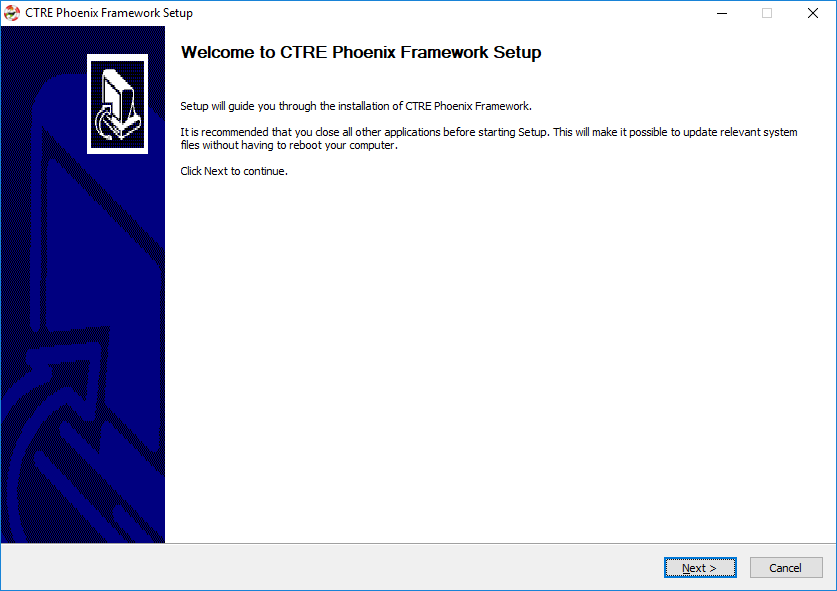
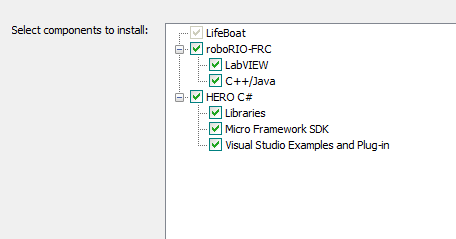
This will look very similar to previous installers - make sure you have the relevant component selected for your programming language.
LV Teams: Make sure LabVIEW is selected. If it is grayed out, then LabVIEW was not installed on the PC.
C++/Java Teams: Make sure C++/Java is selected.
If Visual Studio 2017 (Community/Professional) is detected, HERO C# will be selected. This can be turned off to speed up the installer.
Installer can take anywhere from 30 seconds to 5 minutes depending on which Microsoft runtimes need to be installed.
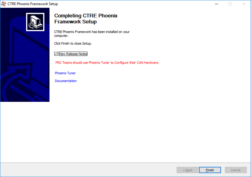
Final page will look like this. The Phoenix Tuner link can be used to open Phoenix Tuner. Alternatively, you can use the Windows Start Menu.
Option 2: Non-Windows Zip (C++/Java)
The zip will contain two folders, “maven” and “vendordeps”. These folders are meant to be inserted into your frc2020 install folder.
See WPI documentation for typical location. https://docs.wpilib.org/en/latest/docs/software/wpilib-overview/3rd-party-libraries.html#the-mechanism-c-java
Copy/paste the maven and vendordeps folder into frc2020 folder. This will override a pre-existing Phoenix installation if present.
Note
This will not install Phoenix Tuner or firmware files. If these are necessary (and they typically are) these can be downloaded separately or consider using the complete Phoenix Installer.
Post Installation Steps
After all workstation installs, the following checks should be followed to confirm proper installation.
FRC C++/Java - Verify Installation
The offline files for vscode are typically installed in:
C:\Users\Public\wpilib\2020\vendordeps\Phoenix.json (File used by vscode to include Phoenix in your project)
C:\Users\Public\wpilib\2020\maven\com\ctre\phoenix (multiple maven-style library files)
Your drive letter may be different than “C:”. After running the Phoenix Installer, the instructions to add or update Phoenix in your robot project must be followed.
FRC LabVIEW – Verify Installation
After running the installer, open a pristine copy of FRC LabVIEW.
Testing the install can be done by opening LabVIEW and confirming the VIs are installed. This can be done by opening an existing project or creating a new project, or opening a single VI in LabVIEW. Whatever the simplest method to getting to the LabVIEW palette.
The CTRE Palette is located in:
WPI Robotics Library -> Third Party.
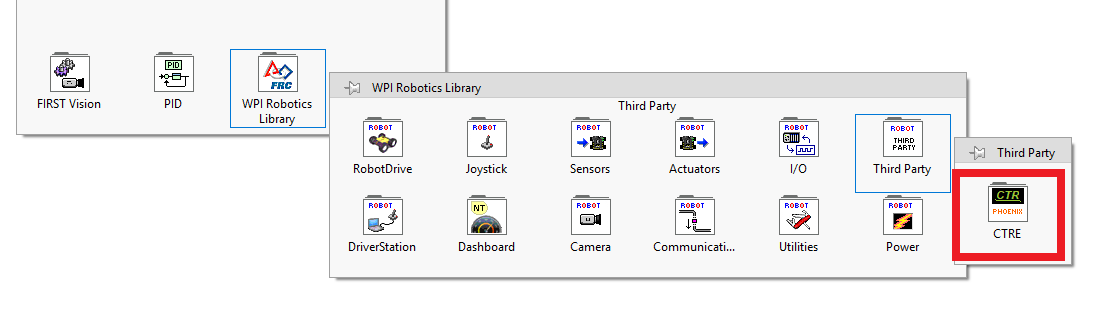
This palette can also be found in:
WPI Robotics Library -> RobotDrive -> MotorControl -> CanMotor
WPI Robotics Library -> Sensors -> Third Party
WPI Robotics Library -> Actuators -> Third Party
FRC Windows – Open Phoenix Tuner
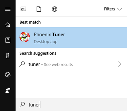
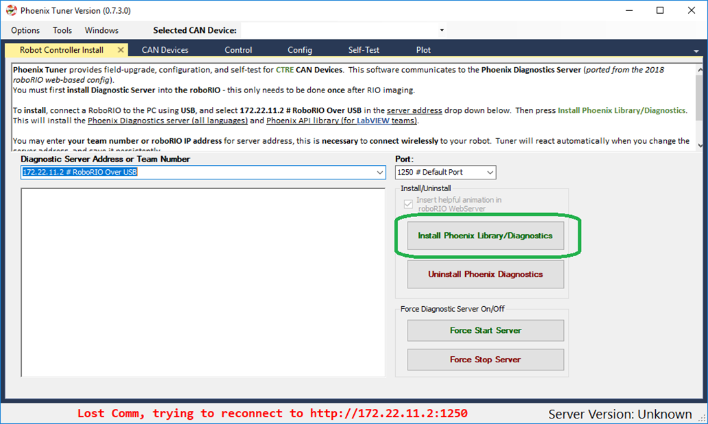
Open Phoenix Tuner
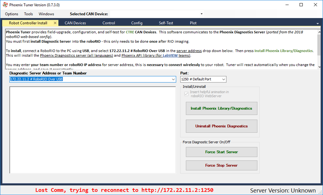
If this is the first time opening application, confirm the following:
the status bar should read “Lost Comm”.
No CAN devices will appear.
The Server version will be unknown.
FRC: VS Code C++/Java
FRC C++/Java – Create a Project
Next we will create a new robot project in vscode and create a Talon SRX. The goal is compile the project only, so hardware is not needed.
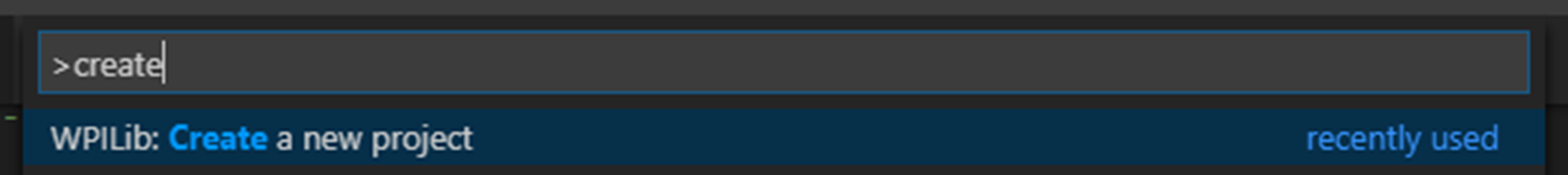
Follow the WPI frc-docs instructions on reaching the create new project. Typically, you can use CNTRL+SHIFT+P to open the VS text bar, and type create to reach the WPI command.
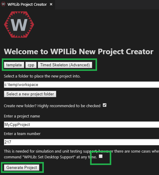
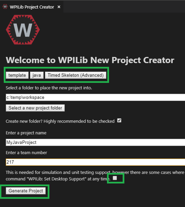
Make sure the desktop checkbox is cleared, Phoenix does not currently support desktop simulation. “Timed Skeleton” is used in this example for sake of simplicity.
Once the project is created, ensure project builds. Testing robot deploy is also useful if robot controller is available.
FRC C++/Java – Add Phoenix
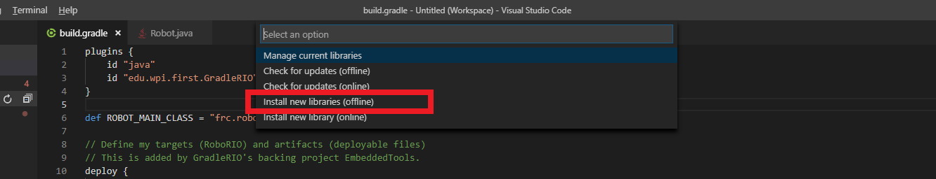
Right-Click on “build.gradle” in the project tree, then select “Manage Vendor Libraries”.

At the top of your screen, a menu will appear. Select “Install new libraries (offline)”.
Tip
Alternatively you can use “Install new libraries (online)” option with https://maven.ctr-electronics.com/release/com/ctre/phoenix/Phoenix-frc2022-latest.json. However this is not recommended as this requires a live Internet connection to use your FRC project.
The menu will now display a list of vendor libraries you can install. Check “CTRE Phoenix”, then click “OK”
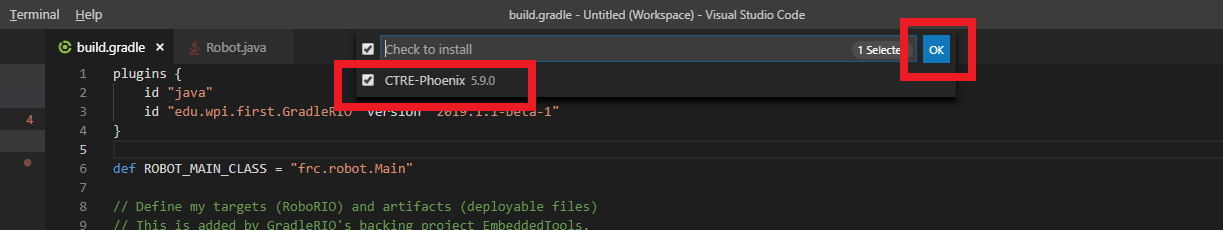
Note
This will bring the library into the project references, however the library will not be loaded if the source code does not create a Phoenix object or call any Phoenix routines. Therefore, you must create a Phoenix object to properly test the install.
Tip
Teams can verify Phoenix is in their robot project by checking for the existence of vendordeps/Phoenix.json in the project directory.
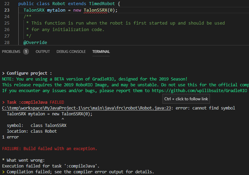
FRC C++ Build Test: Single Talon
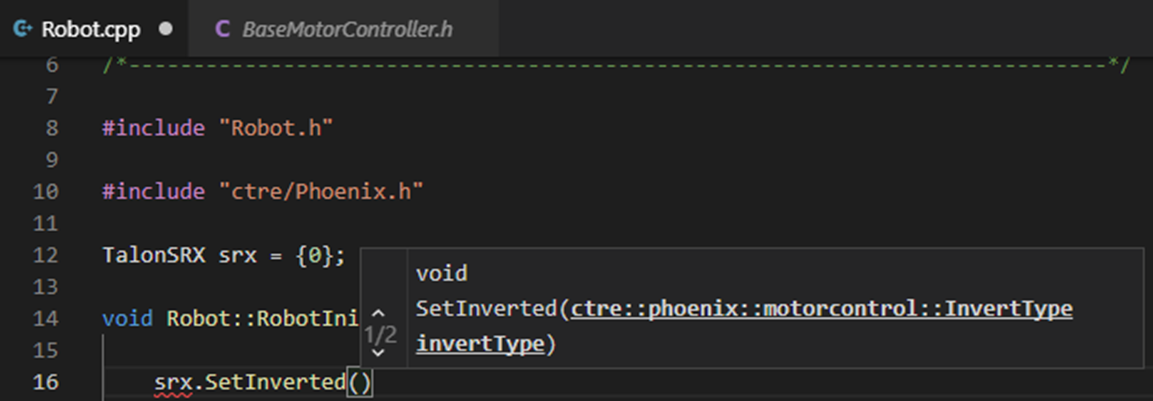
Create a TalonSRX object. The number specified is the Talon’s device ID, however for this test, the device ID is irrelevant.
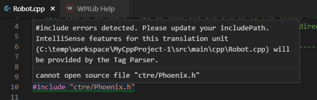
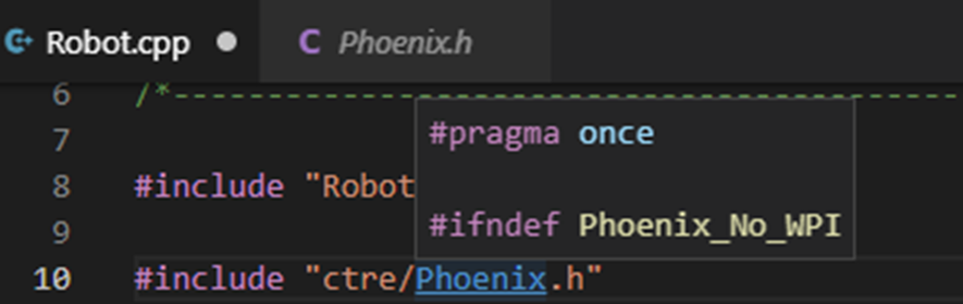
Be sure to include “ctre/Phoenix.h”, otherwise TalonSRX will not be recognized as a valid class type.
Add an example call, take your time to ensure to spell it correctly.
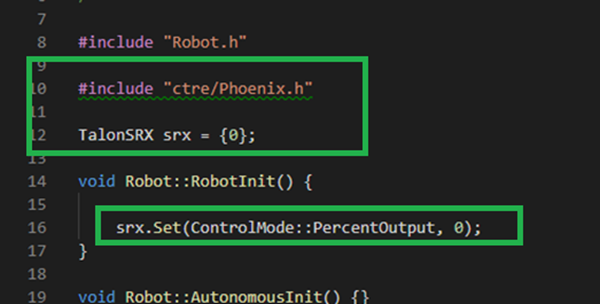
Intellisense may not be functional at this point in time (note the green underline indicating VS did not parse the header).
Tip
To correct this - Close all files in the project - Restart VS Code - Wait ~40s - Reopen source files in VS Code
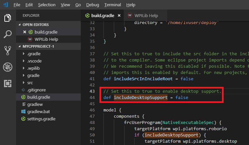
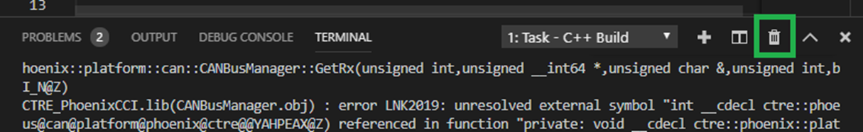
If you see linker errors, then the desktop simulation checkbox was likely checked.
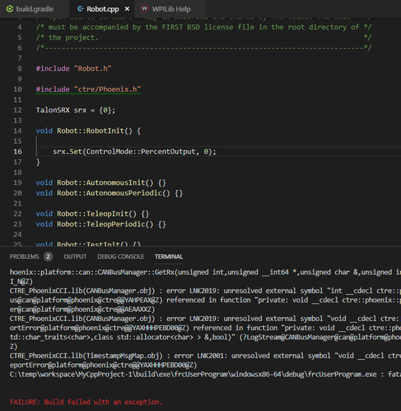
This can be resolved by manually turning off the feature. Set flag to false.
Tip
When resolving compiler/linker errors, press the trash icon first to cleanly erase the previous error lines in the terminal. Or manually scroll the bottom to ensure you are not looking at stale error lines from previously failed builds.
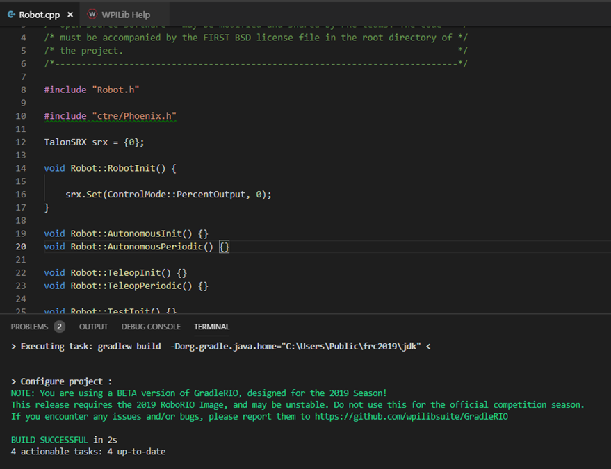
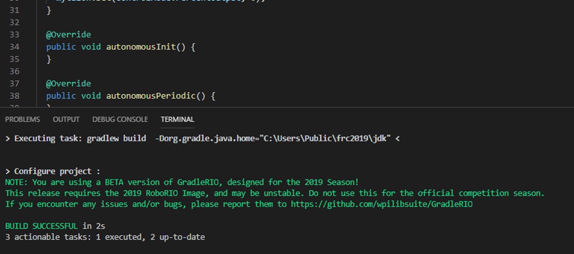
The only reliable way to confirm build was successful is to confirm the BUILD SUCCESSFUL line at the bottom of the TERMINAL.
Note
The problems tab may or may not be clear of errors. Our testing with VSCode has shown that it can report stale or incorrect information while making code changes. Always use the TERMINAL output to determine the health of your compilation and build system.
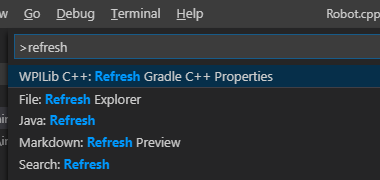
In the event that the intellisense is not resolving symbols (for IDE auto-complete features), restart VSCode.
After restart, routines should be found correctly.
Tip
Headers can be auto-opened by CNTRL+CLICK the include line.
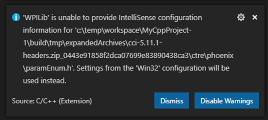
Depending on the version of VS Code used, you may encounter an IntelliSense warning. These can be ignored.
FRC Java Build Test: Single Talon
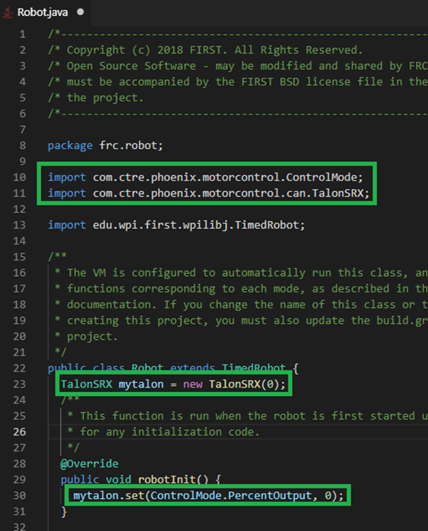
Create a TalonSRX object. The number specified is the Talon’s device ID, however for this test, the device ID is irrelevant.
Typically, you can type “TalonSRX” and watch the intellisense auto pop up. If you press ENTER to select the entry, the IDE may auto insert the import line for you.

Add an example call, take your time to ensure to spell it correctly. Use the intellisense features if available.
Here is the final result.
If you see build errors, carefully find the first erroneous line in the TERMINAL output. Typically, you can CNTRL + click the error line and auto-navigate to the source.
When resolving compiler errors, press the trash icon first to cleanly erase the previous error lines in the terminal. Or manually scroll the bottom to ensure you are not looking at stale error lines from previously failed builds.
The only reliable way to confirm build was successful is to confirm the BUILD SUCCESSFUL line at the bottom of the TERMINAL.
Note
The problems tab may or may not be clear of errors. Our testing with VSCode has shown that it can report stale or incorrect information while making code changes. Always use the TERMINAL output to determine the health of your compilation and build system.
FRC C++/Java - Updating Phoenix
If you already have a previous version of Phoenix installed and you want to update to a newer version, follow these steps. Install the latest version of Phoenix on your PC. Basically, rerun the latest installer (same as section above).
Open your robot program in VS Code.
At the top of your screen, a menu will appear. Select “Check for updates (offline)”.
Tip
Alternatively you can use “Check for updates (online)”. However this is not recommended as this requires a live Internet connection to use your FRC project.
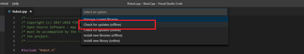
The menu will now display a list of vendor libraries you can update. Check “CTRE Phoenix”, then click “OK”
FRC C++/Java – Test Deploy
Create a Talon SRX (or Pigeon, CANifier, Victor SPX) and attempt to “deploy”. Adding a print statement also helps to confirm you are actually deploying the software displayed in VsCode. Confirm that the software deployed using DriverStation. DS may report firmware-too-old / not-retrieved errors since the hardware has not been setup yet.
FRC: Prepare NI roboRIO
Why prepare Robot Controller?
In the previous 2019 season, preparing the Robot Controller typically meant:
Installing the Phoenix Diagnostics
Installing the Phoenix API into roboRIO (if using LabVIEW).
In the 2020 release of Phoenix, both of these are automatically handled by the library deployment features of WPI Visual Studio Code extensions (C++/Java) and NI LabVIEW.
Phoenix Diagnostics has become a library that is compiled into the FRC robot application. This is a result of the roboRIO CAN bus changes implemented by the NI for 2020. Tuner now communicates with “Phoenix Diagnostic Server” running in the deployed application via an HTTP API.
If the roboRIO does not have a deployed application, a temporary Diagnostic Server application can be deployed from Tuner. This is particularly useful during hardware-bringup.
LabVIEW
NI LabVIEW supports a feature that will automatically deploy the Phoenix API libraries to the roboRIO. After running the installer, 2020 LabVIEW robot projects will automatically install Phoenix into the roboRIO when the program is permanently deployed via “Run As Startup”.
- The steps for first deploy are:
“Build” the FRC Boot-up Deployment
“Run as Startup”
Re-boot the roboRIO (see note below)
Note
After first Run-as-Startup (since imaging the RIO), you may see an error in the Driver Station reporting that the Phoenix libraries are missing. A reboot of the RIO will likely resolve this. We recommend using the “Restart roboRIO” button in the Driver Station.
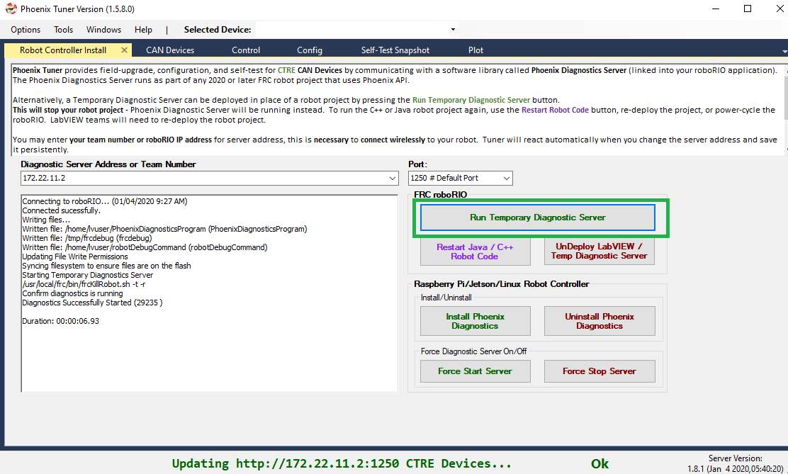
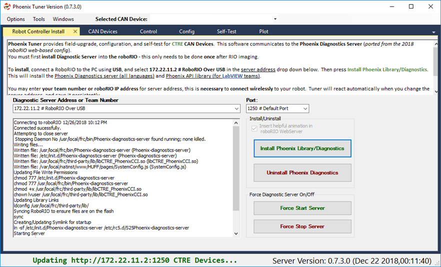
How to prepare Robot Controller
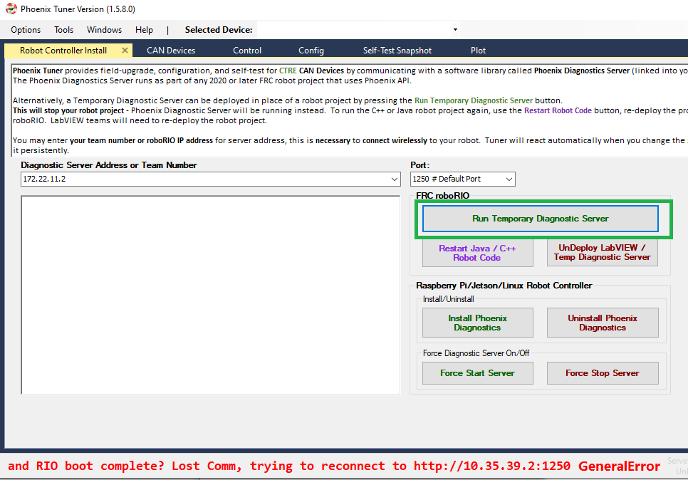
Open Tuner and connect USB between the workstation and the roboRIO.
Select 172.22.11.2 # RoboRIO Over USB and 1250 for the address and port. These are generally selected by default, and typically do not require modification.
Deploy the Temporary Diagnostic Server.
Note
This is unnecessary if a robot application has been deployed already (C++, Java, or LabVIEW).
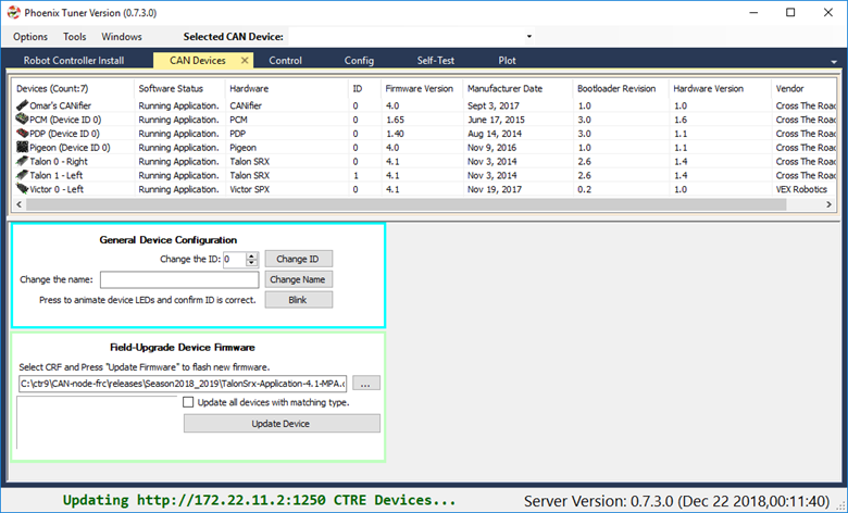
Verify the robot controller - Tuner
After application deployment, Tuner will immediately connect to the roboRIO.
Confirm the bottom status bar is green and healthy, and server version is present.
If there are CAN device present, they will appear. However, it is possible that devices are missing, this will be resolved in the next major section (CAN Bus bring up).
roboRIO Connection (Wi-Fi/Ethernet)
The recommended connection method for control/plotter features is over USB or using static IP (Ethernet/Wi-Fi). The mDNS strategy used by the roboRIO can sometimes fail intermittently which can cause hiccups when submitting HTTP requests to the roboRIO.
Testing has shown that using USB (172.22.11.2) or using static IP address has yielded a greater user experience than the roborio-team-frc.local host name has.
Note
Future releases may have improvements to circumvent the limitations of mDNS.
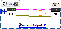
Verify the robot controller - LabVIEW
Create a pristine LabVIEW application. Add a CTRE device to Begin.Vi. For example, create a Talon SRX object, even if the device is not physically present.
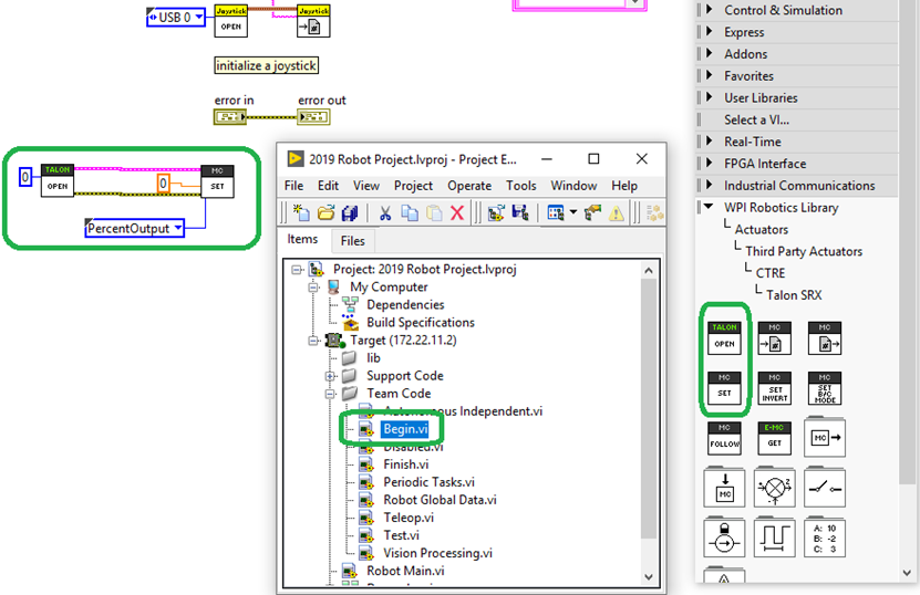
Tip
Drag drop the following into your Begin.vi
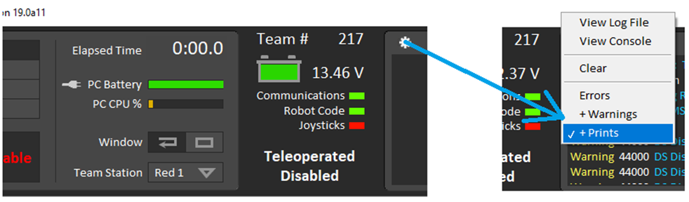
Connect DS and turn on Warnings and Prints by selecting the bottom most option.
Upload the application to the robot controller and check the driver station message log.
If everything is working, the Phoenix Initialization message can be found.
Note
This message will not appear after subsequent “soft” deploy (LabVIEW RAM-only temporary deploys).

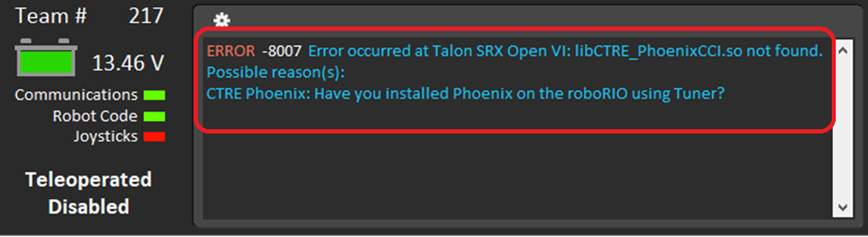
If Phoenix API has not been installed into the robot controller, this message will appear.
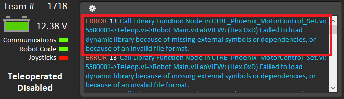
If you have used Phoenix LifeBoat (which should NOT be used), this message will appear. If this occurs you will need to re-image your roboRIO and then re-follow the instructions in this section exactly, without using LifeBoat.
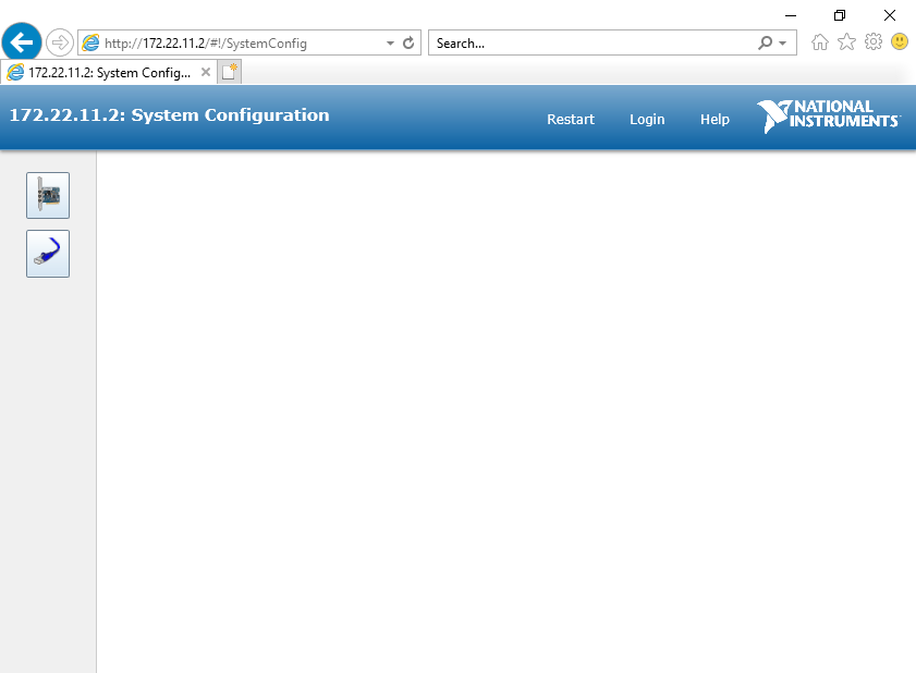
Verify the robot controller - Web page
The Silverlight web interface provided in previous seasons is no longer available. Moving forward, the NI web interface will likely be much simpler.
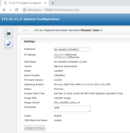
As a result, Phoenix Tuner may embed a small message reminder indicating that CAN features have been moved to Tuner. This will depend on the version of Phoenix.
Typically, the message will disappear after 5 seconds. This will not interfere with normal web page features (IP Config, etc.).
Warning
The roboRIO Web-page does not provide CAN bus support any more as this has been removed by NI. Use Phoenix Tuner instead.
Warning
The roboRIO Web-page does not render correctly if using Internet Explorer (see below). Recommended browsers are Chrome or Firefox.
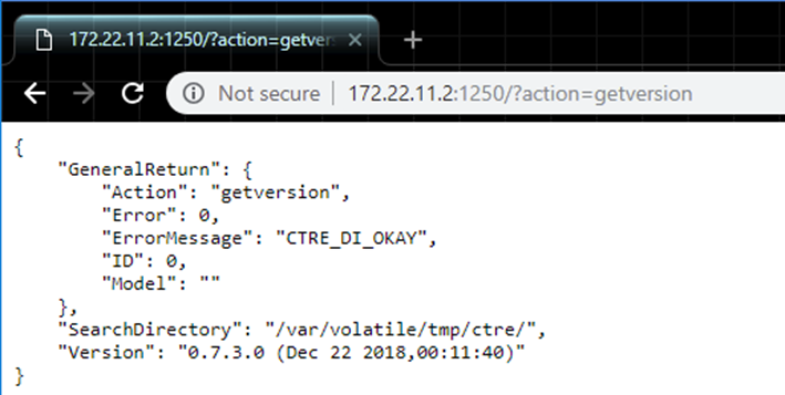
Verify the robot controller - HTTP API
Tuner leverages the HTTP API provided by Phoenix Diagnostics Server.
So technically you have already confirmed this is working.
But, it is worth noting that this HTTP API can potentially be used by third-party software, or even the robot application itself.
Here is a simple get version command and response.
http://172.22.11.2:1250/?action=getversion
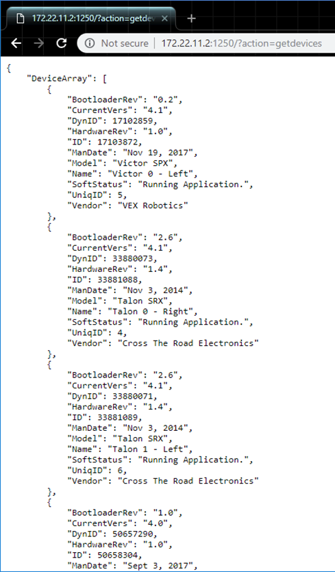
Here is a simple getdevices command and response.
http://172.22.11.2:1250/?action=getdevices
Prepare Linux Robot Controller
Why prepare Linux Robot Controller?
Preparing a Linux robot controller allows CAN Device control without a roboRio for non-FRC use or as a secondary processor that can also directly control CAN Devices while still using the roboRIO for Enable/Disable Signal.
Phoenix Diagnostic Server is necessary for Phoenix Tuner to interact with CTRE CAN Devices. Tuner communicates with “Phoenix Diagnostic Server”, a Linux application that provides an HTTP API.
Supported Linux Controllers
Below are the currently supported Linux hardware platforms. An additional SocketCAN device is necessary to utilize the provided software as-is, otherwise a custom platform library is required.
NVidia Jetson TX2
NVidia Jetson Nano
Raspberry Pi 3
Raspberry Pi 4
It is possible to use other hardware platforms, however hardware and software setup may be different than this documentation.
Note
CTRE currently recommends the CANable for use as a SocketCAN device. More information can be found here: https://canable.io/
How to prepare Hardware?
Jetson TX2
Follow the documentation provided by NVidia to setup the Jetson TX2: https://developer.nvidia.com/embedded/downloads
Raspberry Pi/Jetson Nano
Image your device with the respective image below. Other Images can also be used, although these images have been tested and are known to be supported.
Raspbian Buster Image for Raspberry Pi: Pi Image
Jetson Nano Developer Kit SD Card Image: Nano Image
Etcher (available here) is the recommended tool for flashing the image to an SD card. With Etcher open, select your downloaded image and the SD card target, then click “Flash!”.
Once flashed insert the SD card into your device, set up a user and connect to a Wi-Fi network.
CANable (SocketCAN Device)
Once your controller is ready, it is necessary to setup your SocketCAN device.
To use CANable as a SocketCAN device, update the Canable firmware to “candlelight” using these instructions.
Alternatively you can deploy SocketCAN firmware to a HERO. See our repository on Github.
How to prepare Robot Controller Software?
It is recommended to update your Linux platform software before installing the components necessary for Phoenix.
sudo apt-get update
sudo apt-get upgrade
Next, install the required software packages using the following commands:
CAN Tools
sudo apt-get install can-utilsGit
sudo apt-get install gitcmake (for build support)
sudo apt-get install cmakelibsdl2 (for gamepad support)
sudo apt-get install libsdl2-dev
With the necessary software installed, clone the example repository into the user directory. This example is a basic C++ project that includes all necessary Phoenix libraries and will be used to validate the hardware and software setup.
From the user directory, run: git clone https://github.com/CrossTheRoadElec/Phoenix-Linux-SocketCAN-Example.git
Then navigate into the repo directory: cd ./Phoenix-Linux-SocketCAN-Example/.
To ensure the scripts from our cloned repository can be executed, make sure to enable execution privileges.
chmod +x build.sh
chmod +x clean.sh
chmod +x canableStart.sh
Now we can initialize our SocketCAN interface.
Bring up the interface as socket “can0” by running the CANable start script:
./canableStart.sh
Note
if you see the message Device or resource busy it means the CAN network is already up and requires no further action.
Configure SocketCAN to allow hot swapping
This is necessary to be able to disconnect and reconnect your USB to CAN adapter without running bringing up the CAN network each time your usb to can adapter is reconnected.
Open a new terminal and type cd /etc/network/..
Once inside the network directory type sudo gedit interfaces.
sudo geany interfaces to edit the file.A text editor should open. Add the following lines to the file:
allow-hotplug can0
iface can0 can static
bitrate 1000000
txqueuelen 1000
up /sbin/ip link set $IFACE down
up /sbin/ip link set $IFACE up type can
How to validate SocketCAN functionality?
Make sure you have at least one CTRE CAN device connected for validation of the CAN network. With no CAN traffic, device LEDs will be blinking RED.
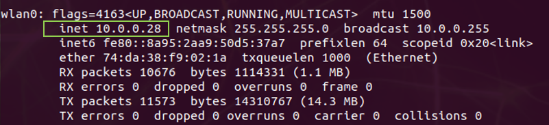
Use the ifconfig command to list network interfaces, where you can see the status of the CAN socket.
The interfaces list should contain an entry for “can0” and should look like this:
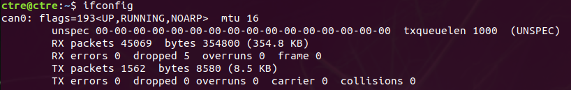
Type cansend can0 999#DEADBEEF to send a test CAN frame. Your CAN devices should now blink orange since a valid CAN message has been seen.
Use candump can0 to see all incoming CAN traffic, which should display all periodic information being sent by a CAN Device.
You should see a constant stream of messages similar to this:

Running the SocketCan Example
Build the example with ./build.sh.
Then run the example with ./bin/example.
You’re now running Phoenix on your Linux device. Confirm there are no error messages being sent to console output.
Note
You may see error messages if your CAN devices are not yet configured and firmware updated. Follow the Bring Up: CAN section to setup your CAN devices.
Warning
If your CTRE CAN devices were previously used with a roboRIO it is likely they are FRC locked and will not enable without a roboRIO on the CAN bus. See Confirm FRC Unlock for instructions to confirm FRC unlock.
You can stop your Program with Ctrl+z.
Modifying the SocketCan Example
To modify the example Open the file explorer and navigate to the Phoenix-Linux-SocketCAN-Example folder.
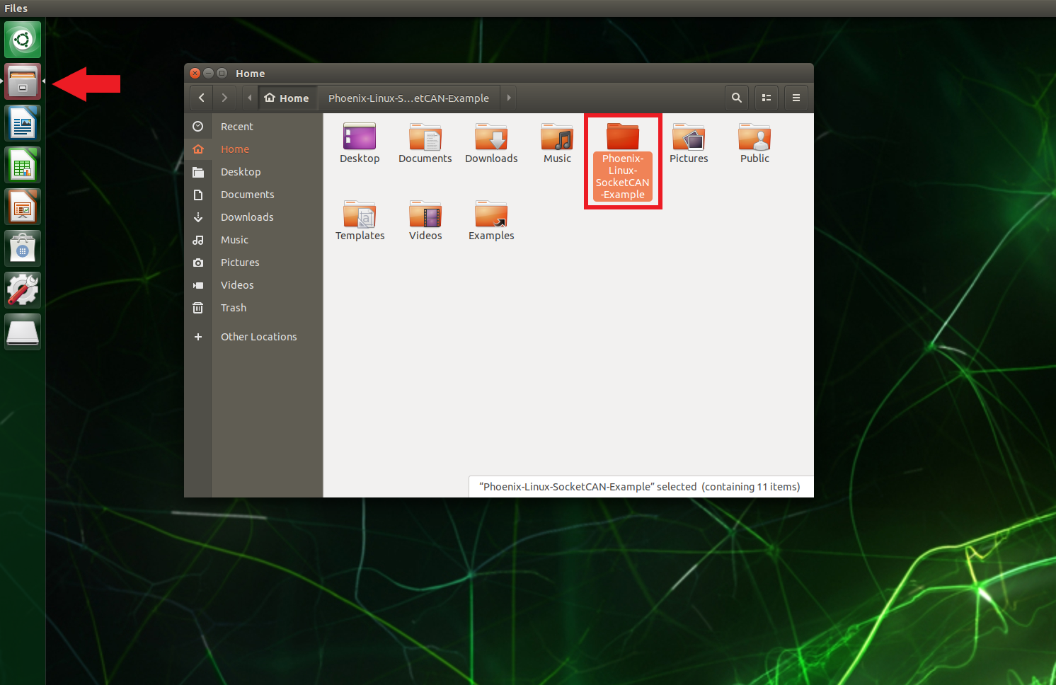
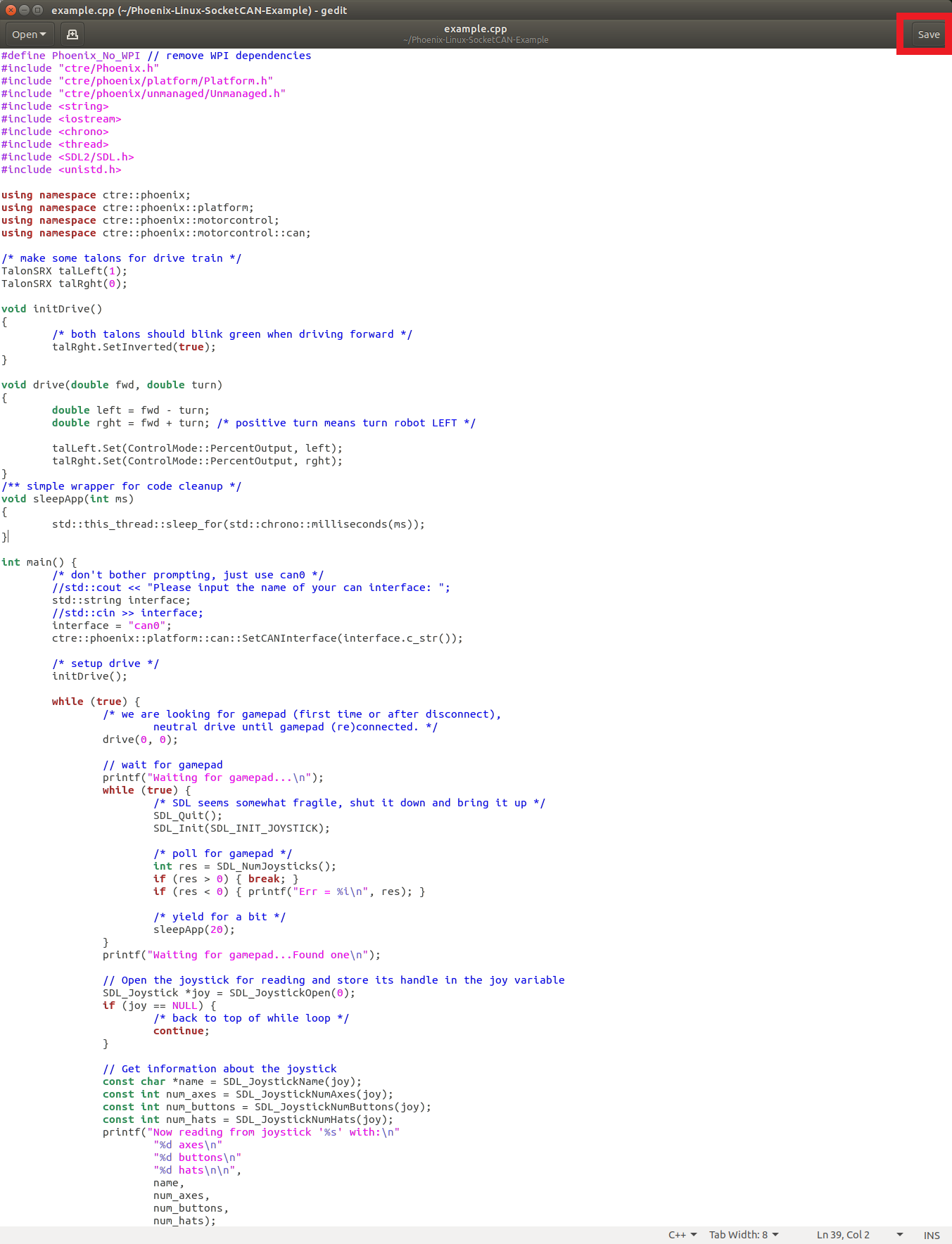
The example is a simple program, so all of the code is contained within example.cpp. Edit this file to modify the program.
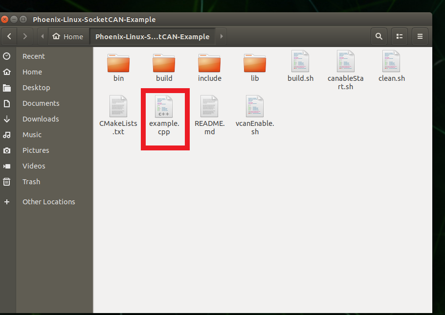
After modifying the file click the Save button in the top right corner then Go back to Running the SocketCAN Example to run your modified example.
How to setup Phoenix Tuner?
With the CAN network up and running, Phoenix Tuner can be used with the Linux Robot Controller in the same manner as the roboRIO.
Note
SSH must be enabled on the Linux Robot Controller to perform a field upgrade or modify a device’s configuration using Phoenix Tuner.
Connect both the Linux Robot Controller and Windows machine to the same network via WiFi or and ethernet connection.
Enter the IP Address or Name of the Linux Robot Controller into Phoenix tuner.
Tip
To find the IP address in Linux, run the ifconfig command to display network interfaces. The IP address will be listed under a ‘lan’ or ‘wlan’ entry and listed as inet.
Setting up the Phoenix Diagnostics Server
The Phoenix Diagnostics Server is an HTTP server that communicates with the Phoenix Tuner. There are two versions of the server: a standalone version installed through Phoenix Tuner (legacy), and a version built into your user program (latest). Only one version of the diagnostics server may be running at any given time. We recommend you run the diagnostics server through your user program.
You can disable the diagnostics server in your program by adding c_SetPhoenixDiagnosticsStartTime(-1); to the start
of your main method. The line is commented out in the example program.
Warning
The instructions below are available for legacy support. We recommend you instead run the Phoenix Diagnostics Server in your user program.
Warning
The legacy instructions below currently do not work. See: https://github.com/CrossTheRoadElec/Phoenix-Linux-SocketCAN-Example/issues/15
To install the standalone diagnostics server:
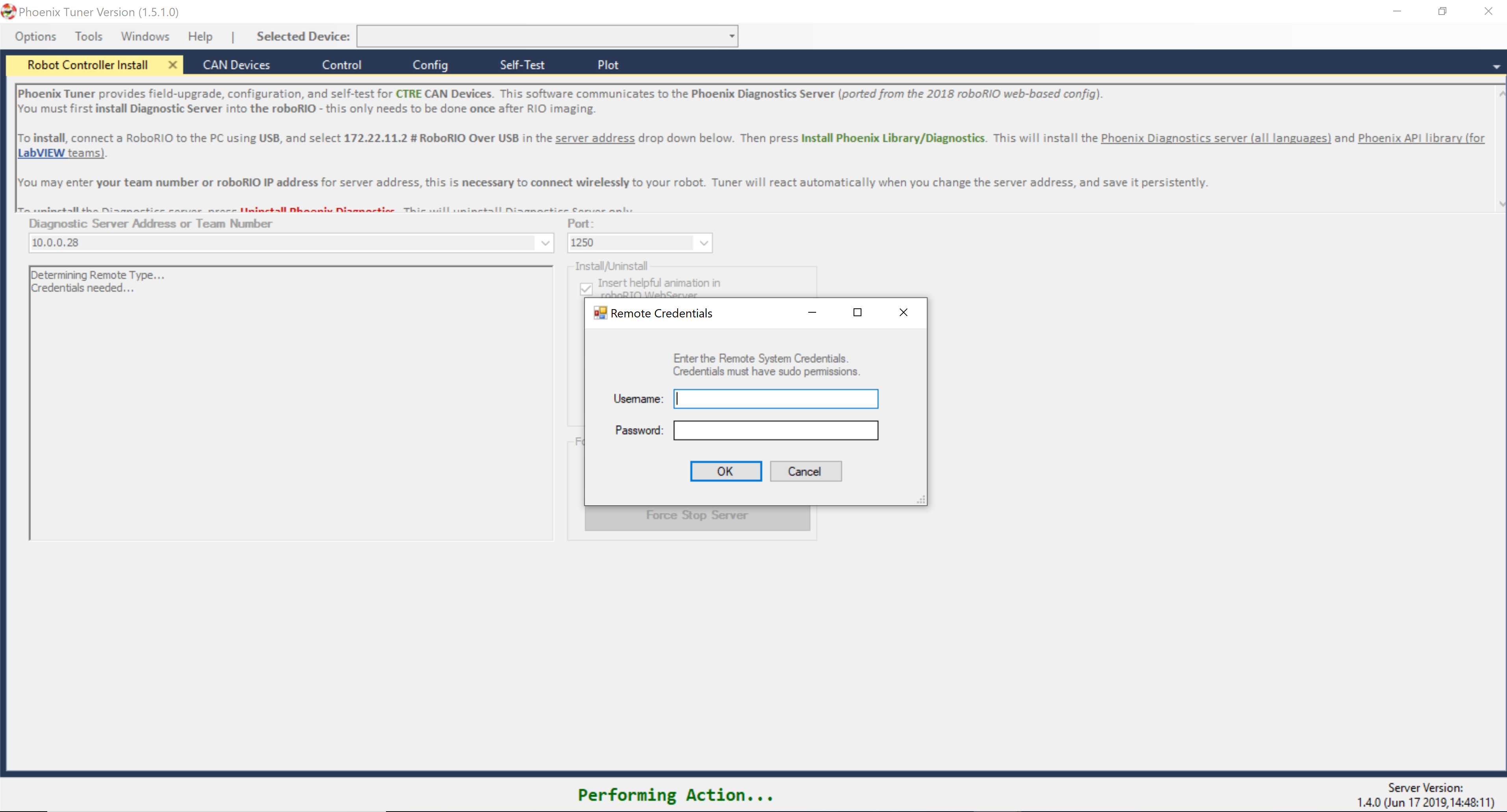
Press the Install button.
Enter your username and password when prompted.
Note
The user must have sudo permissions to successfully install.
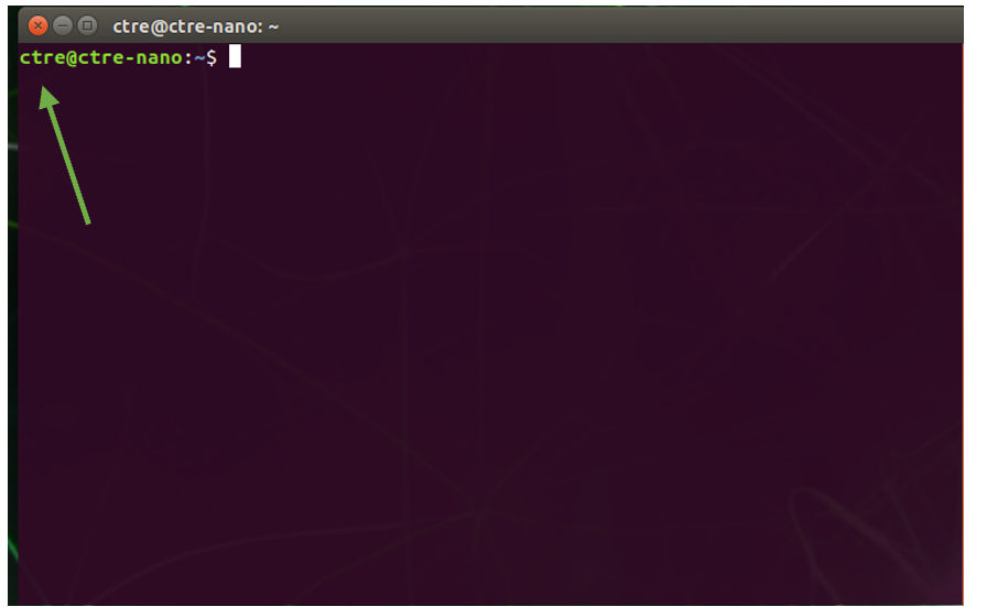
Note
To find your username look at the text before the @ in the terminal. For example, in this terminal the user is ctre.
Tuner will then install and start the diagnostics server on the device.
The diagnostics server is now installed and running on your device.
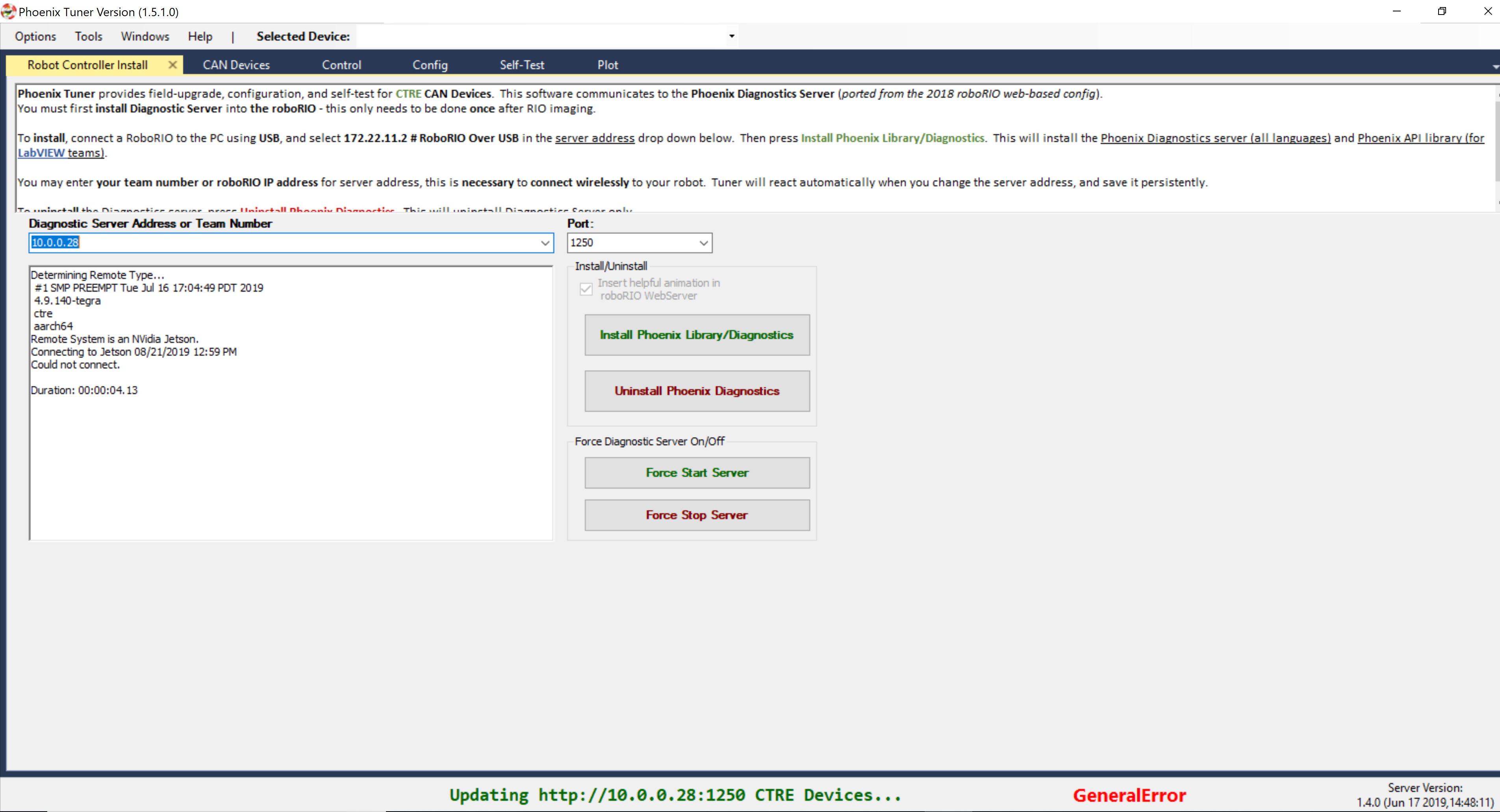
Verify the robot controller - Tuner
After installation is complete, Tuner will immediately connect to your device.
Confirm the bottom status bar is green and healthy, and server version is present. If this is not the case, you may need to re-start the Diagnostic Server by using the “Force Stop Server” and “Force Start Server” buttons.
If there are CAN device present they will appear in the “CAN Devices” tab. However, it is possible that devices will appear to be missing - this will be resolved in “Bring Up: CAN Bus”.
Initial Hardware Testing
For your competition team to have the best chance of success, hardware components should be tested as soon as they are received. This is generally done by:
Powering up the device and confirming LED states.
Ensuring hardware shows up in Tuner if wired to CAN Bus.
Drive outputs / drive motor in both directions (if motor controller).
This is explained in the sections below, but it is worth pointing out how important this step is. It is in your team’s best interest to test ALL purchased robot components immediately and in isolation. Here are the reasons why:
Robot replacement components should be in a state of readiness. Otherwise a replacement during competition can yield erroneous behavior.
Many robot components (in general) have fixed warranty periods, and replacements must be done within them.
Confirming devices are functional before handing them to students ensures best chance of success. If a student later damages hardware, they need to understand how they did it to ensure it does not happen again. Without initial validation, you can’t determine root-cause.
Much of this is done during the “bring-up” phase of the robot. However, there is much validation a team can do long before the robot takes form.
Unfortunately, there are many teams that do not perform this step, and end up isolating devices and re-implementing their cable solutions at competition, because this was not done during robot bring up.
Note
“Bring up / Board bring up / Hardware bring up” is an engineering colloquial phrase. It is the initial setup and validation phase of your bench or robot setup.
Bring Up: CAN Bus
Now that all of the software is installed and verified, the next major step is to setup hardware and firmware.
Understand the goal
At this point we want to have reliable communication with CAN devices. There are typically two failure modes that must be resolved:
There are same-model devices on the bus with the same device ID (devices have a default device ID of ‘0’).
CAN bus is not wired correctly / robustly.
This is why during hardware validation, you will likely have to isolate each device to assign a unique device ID.
Note
CTRE software has the ability to resolve device ID conflicts without device isolation, and CAN bus is capable of reporting the health of the CAN bus (see Driver Station lightening tab). However, the problem is when both root-causes are occurring at the same time, this can confuse students who have no experience with CAN bus systems.
Note
Many teams will preassign and update devices (Talon SRXs for example) long before the robot takes form. This is also a great task for new students who need to start learning the control system (with the appropriate mentor oversight to ensure hardware does not get damaged).
Note
Label the devices appropriately so there is no guessing which device ID is what. Don’t have a label maker? Use tape and/or Sharpie (sharpie marks can be removed with alcohol).
Warning
Talon SRX and Talon FX must use unique device IDs for Phoenix API to function correctly. This design decision was made so that teams could use the existing TalonSRX class for control.
Check your wiring
Specific wiring instructions can be found in the user manual of each product, but there are common steps that must be followed for all devices:
If connectors are used for CANBus, tug-test each individual crimped wire one at a time. Bad crimps/connection points are the most common cause of intermittent connection issues.
Confirm red and black are not flipped. Motor Controllers typically are not reverse power protected.
Confirm battery voltage is adequate (through Driver Station or through voltmeter).
Manually inspect and confirm that green-connects-to-green and yellow-connects-to-yellow at every connection point. Flipping/mixing green and yellow is a common failure point during hardware bring up.
Confirm breakers are installed in the PDP where appropriate.
Measure resistance between CANH and CANL when system is not powered (should measure ~60Ω). If the measurement is 120Ω, then confirm both RIO and PDP are in circuit, and PDP jumper is in the correct location.
Power up and check LEDs
If you haven’t already, power up the platform (robot, bench setup, etc.) and confirm LEDs are illuminated (at all) on all devices.
You may find many of them are blinking or “blipping” red (no communication).
Tip
If you are color-blind or unable to determine color-state, grab another team member to assist you.
Note
If using Ribbon cabled Pigeon IMUs, Pigeon LEDs will reflect the ribbon cable, not the CAN bus. At which point any comm issue with Pigeon will be resolved under section Bring Up: Pigeon IMU.
Open Phoenix Tuner
Navigate to the CAN devices page.
This capture is taken with no devices connected to the roboRIO. roboRIO will take around 30 seconds to boot.
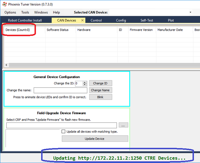
LEDs are red – now what?
We need to rule out same-id versus bad-bus-wiring. There are two approaches. Approach 1 will help troubleshoot bad wiring and common IDs. Approach 2 will only be effective in troubleshooting common IDs. But this method is noteworthy because it is simple/quick (no wiring changes, just pull breakers).
The specific instructions for changing device ID are in the next section. Review this if needed.
Approach 1 (best)
Procedure:
Physically connect CAN bus from roboRIO to one device only. Circumvent your wiring if need be.
Power boot robot/bench setup.
Open Phoenix Tuner and wait for connection (roboRIO may take ~30 seconds to boot)
Open CAN devices tab
Confirm if CAN device appears.
Use Tuner to change the device ID
Label the new ID on the physical device
Repeat this procedure for every device, one at a time.
If you find a particular device where communication is not possible, scrutinize device’s power and CAN connection to roboRIO. Make the test setup so simple that the only failure mode possible is within the device itself.
Note
Typically, there must be two termination resistors at each end of the bus. One is in the RIO and one is in the PDP. But during bring-up, if you keep your harness short (such as the CAN pigtail leads from a single Talon) then the internal resistor in the RIO is adequate.
Approach 2 (easier)
Procedure:
Leave CAN bus wiring as is.
Pull breakers and PCM fuse from PDP.
Disconnect CAN bus pigtail from PDP.
Pick the first device to power up and restore breaker/fuse/pigtail so that only this CAN device is powered.
Power boot robot/bench setup.
Open Phoenix Tuner and wait for connection (roboRIO may take ~30 seconds to boot)
Open CAN devices tab
Confirm if CAN device appears. If device does not appear, scrutinize device’s power and CAN connection to roboRIO.
Use Tuner to change the device ID
Label the new ID on the physical device
Repeat this procedure for every device.
If you find a particular device or section of devices where communication is not possible, then the CAN bus wiring needs to be re-inspected. Remember to “flick” / “shake” / “jostle” the CAN wiring in various sections to attempt to reproduce red LED blips. This is a sure sign of loose contact points.
If you are able to detect and change device ID on your devices individually, begin piecing your CAN bus together. Start with roboRIO <—-> device <—> PDP, to ensure termination exists at both ends. Then introduce the remaining devices until a failure is observed or until all devices are in-circuit.
If introducing a new device creates a failure symptom, scrutinize that device by replacing it, inspecting common wires, and inspecting power.
Note
If 2014 PDP is the only device that does not appear or has red LEDs, see PDP boot up section for specific failure mode.
Note
If ribbon cable Pigeon does not appear, it likely is because Talon has old firmware.
At the end of this section, all devices should appear (notwithstanding the above notes) and device LEDs should not be red. PCM, Talon, Victor, Pigeon, and CANifier typically blink orange when they are healthy and not controlled. PDP may be orange or green depending on its sticky faults.
Set Device IDs
Note
A CTRE device can have an ID from 0 to 62. If you select an invalid ID, you will generally get an immediate prompt.
Below we see several devices, however the physical robot has 19 actual devices. Because all the Talons have a device ID of ‘0’, the do not show up as unique hardware. This must be resolved before you can attempt utilizing them.
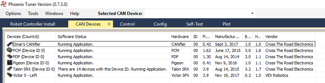
Note
We recommend isolating each device and assigning a unique ID first. But in the event there is a conflict, expect an entry mentioning multiple devices. When selecting a device, the actually physical device selected will be the conflict-id device that booted last. You can use this information to control which Talon you are resolving by power cycling the conflict device, then changing its ID in Tuner.
Select the device and use the numeric entry to change the ID. Note the text will change blue when you do this. Then press “Change ID” to apply the changes.
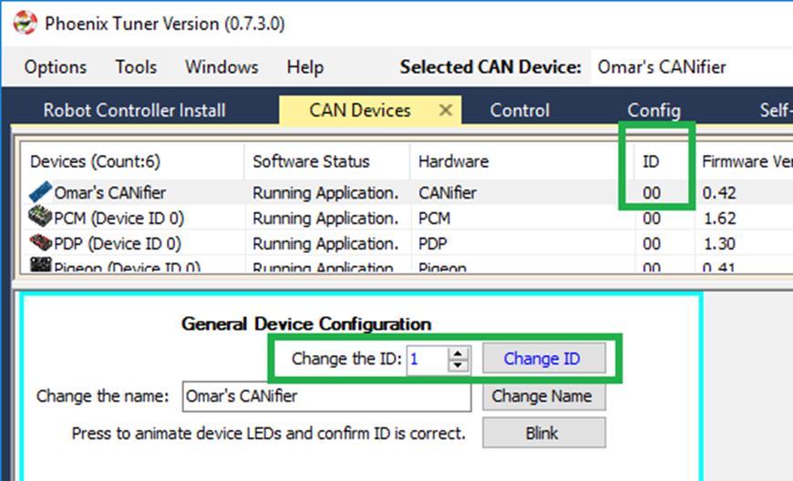
If operation completes, an OK will appear in the bottom status bar (this is true of all operations). Also note the ID has updated in the device list, and the ID text is now black again.
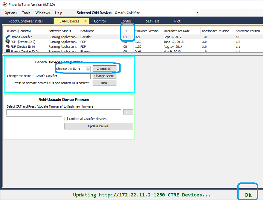
Tip
All production CTRE hardware ships with a default ID of ‘0’. As a result, it is useful to start your devices at device ID ‘1‘, so you can cleanly add another out-of-box device without introducing a conflict.
When complete, make sure every device is visible in the view. Use the Blink button on each device to confirm the ID matches the expected physical device.
Note
The device count is present in the top left corner of the device list. Use this to quickly confirm all devices are present.
Note
If ribbon-cabled pigeon is not present, then the host talon likely has old firmware.

Field upgrade devices
At this point all devices are present, but the firmware is likely old.
The 2020 season has 20.X firmware for Talon FX, Talon SRX, Victor SPX, CANCoder, CANifier, and Pigeon IMU. Moving forward, the first number of the version will represent the season (next year’s 2021 firmware will be 21.X).
20.X firmware is required for all motor controllers and CANCoder. 20.X is also recommended for CANifier and Pigeon IMU.
Note
Latest PDP is 1.40. PDP typically ship with 1.30. 1.40 has all of the signals read by the WPILib software, and will tare the current measures so current will read 0 instead of ~1-2 amps when there is no current-draw. Updating to 1.40 is recommended.
Note
Latest PCM is 1.65. PCM typically ship with 1.62. Firmware 1.65 has an improvement where hardware-revision 1.6 PCMs will not-interrupt compressor when blacklisting a shorted solenoid channel. Older revisions will pause the compressor in order to safely sticky-fault, new revisions have no need to do this (if firmware is up to date).
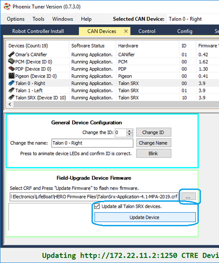
Select the CRF under the Field-upgrade section then press Update Device. The CRFs are available in multiple places, and likely are already on your PC/ See section “Device Firmware Files (crf)”.
If there are multiple devices of same type (multiple Talon SRXs for example), you may check Update all devices. This will automatically iterate through all the devices of the same type, and update them. If a device field-upgrade fails, then the operation will complete. Confirm Firmware Version column in the device list after field-upgrade.
Note
Each device takes approximately 15 seconds to field-upgrade.
When complete every device should have latest firmware.
Pick device names (optional)
The device name can also be changed for certain device types: - CANifier - Pigeon IMU (on CAN bus only) - Talon SRX and Victor SPX
Note
PDP and PCM do not support this.
Note
Ribbon cabled Pigeon IMUs do not support this.
Note
To re-default the custom name, clear the “Name” text entry so it is blank and press “Save”.
Self-test Snapshot
At this point every device should be present on the bus, and updated to latest. This is an opportune time to test the Self-test Snapshot feature of each device.
Select each device either in the device list, or using the dropdown at the center-top. This dropdown is convenient as it is accessible regardless of how the tabs are docked with Tuner.
Note
If you press the “Selected CAN device” text next to dropdown, you will be taken back to the CAN Devices tab.
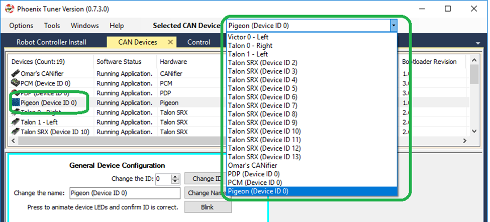
Navigate to the Self-test Snapshot tab. If Self-test Snapshot tab is not present, use the Windows menu bar to reopen it.
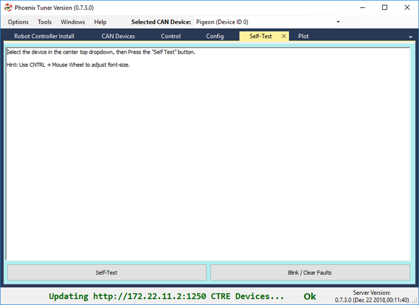
Press Self-test Snapshot button and confirm the results.
Note
This Pigeon has not had its firmware updated, this is reported at the top.
You can also use the Blink/Clear faults button to blink the selected device and clear any previously logged sticky faults.
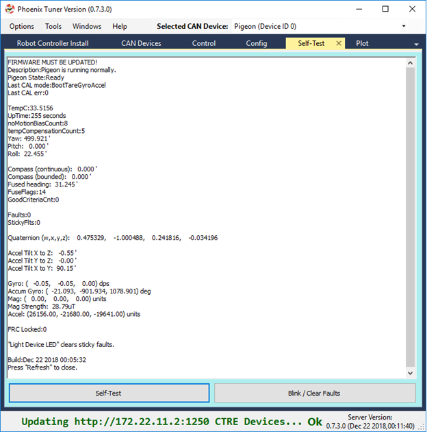
Driver Station Versions Page
It is worth mentioning there is basic support of reporting the CAN devices and their versions in the diagnostics tab of the Driver Station.
If there is a mixed collection of firmware versions for a given product type, the version will report “Inconsistent”.
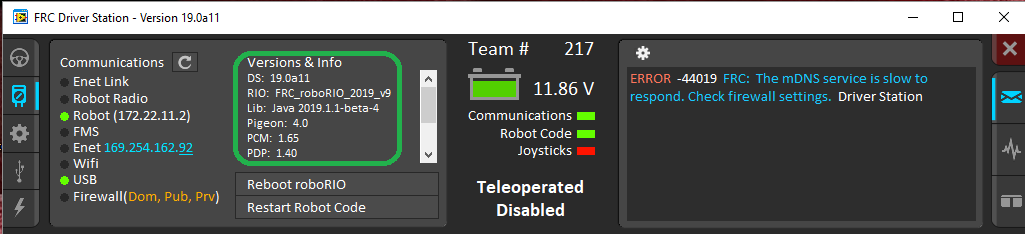
Note
The recommended method for confirming firmware versions is to use Phoenix Tuner.
Note
There is a known issue where ribbon-cabled Pigeons may erroneously report as a Talon. Since this is not a critical feature of the Driver Station, this should not be problematic for FRC teams.
Bring Up: PCM
At this point PCM will have firmware 1.62 or 1.65 (latest). Open Phoenix Tuner to confirm.
Phoenix Tuner Self-test Snapshot
Press Self-test Snapshot to confirm solenoid states, compressor state ,and battery/current measurements. Since device is not enabled, no outputs should assert.

Note
In this view, the Self-test Snapshot was docked to the right. If CAN Devices width is shrunk small enough, the field-upgrade and Device ID options are hidden and the list view becomes collapsed. This way you can still use the device list as an alternative to the center-top dropdown.
The next step is to get the compressor and solenoids operational.
Create a Solenoid object in LabVIEW/C++/Java and set channel 0 to true.
import edu.wpi.first.wpilibj.Solenoid;
public class Robot extends TimedRobot {
    Solenoid _solenoid = new Solenoid(0, 0); // first number is the PCM ID (usually zero), second number is the solenoid channel

    public void teleopPeriodic() {
        _solenoid.set(true);
    }
Tip
Image below can be dragged/dropped into LabVIEW editor.
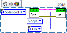
Then confirm using the Solenoid LED on the PCM and Self-test Snapshot in Tuner.
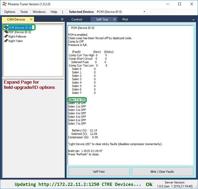
Generally creating a solenoid object is sufficient for the compressor features to function. In order for the compressor output to activate, all of the following conditions must be met:
The robot is enabled via the Driver Station
Robot application has created a solenoid (or compressor object) with the correct PCM device ID.
PCM must be powered/wired to CAN Bus.
Pressure-switch reads too-low (can be confirmed in Self-test Snapshot).
No compressor related faults occur (can be confirmed in Self-test Snapshot)
Tip
Creating a compressor object is not necessary, but can be useful to force the compressor off despite pressure reading too-low with the setClosedLoopControl routine/VI. This can be useful for robot power management during critical operations.
import edu.wpi.first.wpilibj.Compressor;
public class Robot extends TimedRobot {
    Compressor _compressor = new Compressor();

    public void teleopPeriodic() {
        _compressor.setClosedLoopControl(false); //This will force the compressor off
    }
Tip
Image below can be dragged/dropped into LabVIEW editor.
Bring Up: PDP
At this point PDP will have firmware 1.40 (latest). Open Phoenix Tuner to confirm.
Use Self-test Snapshot to confirm reasonable values for current and voltage.
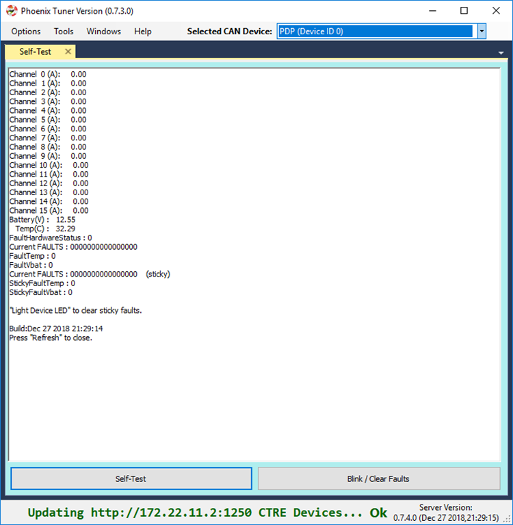
Getting sensor data
Sensor data can also be retrieved using the base FRC API available in LabVIEW/C++/Java. See WPI/NI/FRC documentation for how.
DriverStation Logs
Driver Station logs are automatically generated during normal FRC use. This includes current logging on all PDP Wago channels. Review WPI/NI/FRC documentation for how leverage this.
2015 Kick off Kit PDPs
There is a known issue with 2015 Kickoff-Kit PDPs where the PDP will not appear on CAN bus and/or LEDs will be red, despite all other devices on the CAN bus functioning properly. This is due to an ESD vulnerability that only exists in the initial manufacture run in 2014. Every season PDP afterwards does not have this issue.
Manufacture date of the PDP can be checked in Tuner. Any PDP with a manufacture date of August 14, 2014 may have this issue. No other PDPs (even those with other 2014 manufacture dates) are known to be affected.
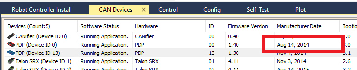
These PDPs do correctly provide power and terminate the CAN bus with no compromises. However, the current measurement features may not be correct or available on this version of PDP. If such a PDP is re-used or re-purposed, we recommend using it on your practice robot or for bench setups, and not for competition.
Bring Up: Pigeon IMU
Power Boot
Power boot the robot and wait for Pigeon IMU LED pattern indicating device has settled. This will appear as a symmetric blink pattern (equal time on each side’s LED). If the LED strobe is weighted to one side (more time on one side than the other) then IMU is still settling. Typical settle time is four seconds.
Warning
Ribbon cabled Pigeon may not appear in CAN devices if Talon SRX firmware is too old.
Warning
Ribbon cabled Pigeon may not work as a remote sensor unless Pigeon Firmware is at least 4.13.
Phoenix Tuner
Open Phoenix tuner and use the Self-test Snapshot feature to confirm values. Rotate IMU and confirm Yaw moves as expected.
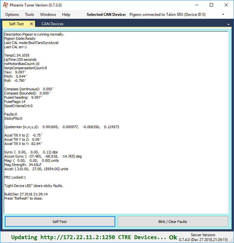
Note
Moving counter-clockwise is interpreted as a positive change.
Pigeon API
Create a Pigeon IMU object in your robot application and poll the Yaw value.
Warning
In a competition robot application it is strongly recommended to first confirm that getState() yields a Ready State. Otherwise the IMU values will not be useful.
import com.ctre.phoenix.sensors.PigeonIMU;
public class Robot extends TimedRobot {
    PigeonIMU _pigeon = new PigeonIMU(0);
    int _loopCount = 0;

    public void teleopPeriodic() {
        if(_loopCount++ > 10)
        {
            _loopCount = 0;
            double[] ypr = new double[3];
            _pigeon.getYawPitchRoll(ypr);
            System.out.println("Pigeon Yaw is: " + ypr[0]);
        }
    }
Tip
Image below can be dragged/dropped into LabVIEW editor.
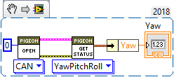
Confirm that the output matches the Self-test Snapshot results.
If using LabVIEW plotter or SmartDash plotting, send the Yaw value into the plotted channel. Then confirm Yaw value provides a smooth curve while robot is rotated by hand.
Temperature Calibration
The greatest source of yaw drift in the FRC use case is drift due to changes in temperature. This can be compensated by running the temperature self-calibration once.
In previous seasons this can be invoked via Phoenix API.

However, starting in 2019, you can manually enter temperature compensation mode by opening the Pigeon IMU Cal tab (go to Windows in the top menu bar).
Select the specific Pigeon in the top drop down, and press the Enter Temperature Calibration button. Self-test Snapshot can be used to monitor the progress.
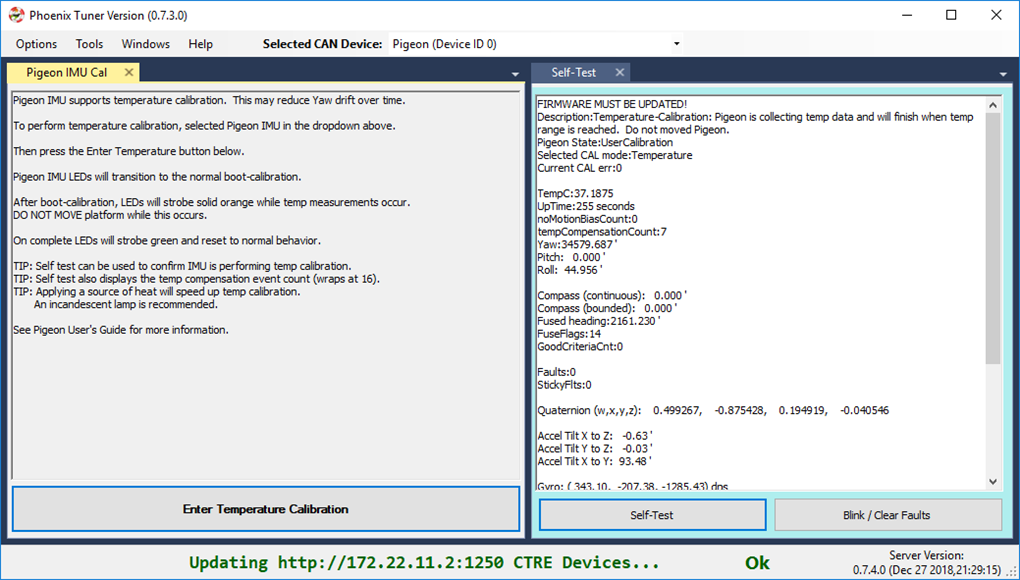
Note
There is no harm in starting a temp calibration, and aborting by power cycling. Previous temp calibration (if present) is overridden at the very end of the procedure. See Self-test Snapshot for current state of Temperature Calibration and Compensation.
Temperature Calibration procedure
When temperature-calibrating the Pigeon, the user should first observe the impact of temperature by cleanly booting the system and observing the critical values (such as yaw) while heating the Pigeon. This can be done by self-testing the Pigeon in Phoenix Tuner or printing the critical values in a robot application.
Place the Pigeon on a reasonably level surface such that it stays still.
After it boot calibrates, heat the Pigeon. A simple off the shelf halogen desk lamp is sufficient to heat.
Observe the critical values as the temperature increases. Some IMU chips are very temperature sensitive and will experience a drift in yaw by over 40 degrees, while others may not drift at all.
After having observed the impact of temperature on the critical values, you can go about calibrating it from that drift.
Ensure Pigeon is cool before beginning temperature calibration. This can be confirmed with a Self-test Snapshot or by printing the temperature in a robot application.
Enter temperature calibration mode. This is done either using the API or using Phoenix Tuner
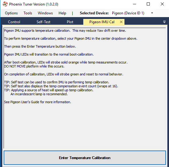
Heat the Pigeon.
Once the Pigeon has seen a sufficient range of temperatures, it will momentarily blink green, then cleanly boot-calibrate.
Perform a Self-test Snapshot on the Pigeon. It should read “Temperature calibration exists” along with a description of whether it will use it or not and for what reason if not.
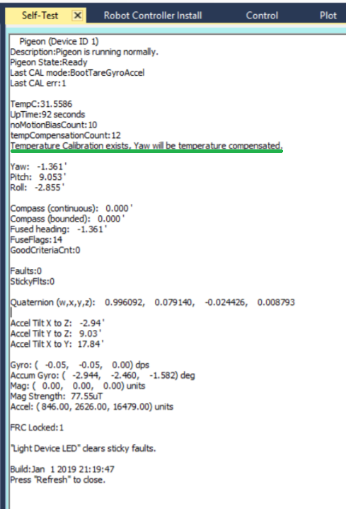
After the Pigeon has boot-calibrated, re-observe the effect of temperature on the critical values’ drift using the above procedure.
While re-observing, notice the tempCompensationCount tracker tick up as the Pigeon compensates for temperature.
Bring Up: CANifier
Phoenix Tuner
Using Self-test Snapshot, confirm all sensor inputs required by the robot application.
If using Limit switches, assert each switch one at time. Self-test Snapshot after each transition to confirm wiring.
If using Quadrature or Pulse width sensor, rotate sensor while performing Self-test Snapshot to confirm sensor values.
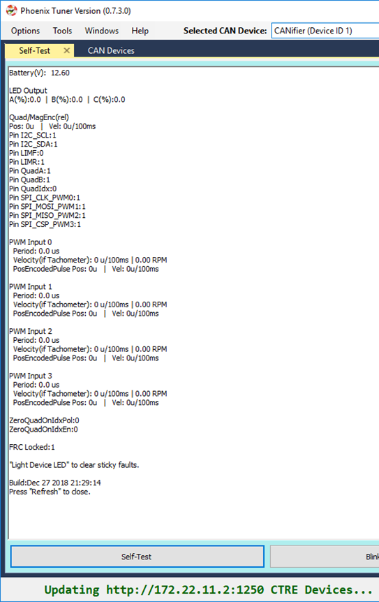
LED Strip Control
See CANifier user’s guide for wiring and controlling LED Strip.
CANifier API
Create a CANifier object in your robot application and poll whatever sensor you have connected to it or the bus voltage
import com.ctre.phoenix.CANifier;
public class Robot extends TimedRobot {
    CANifier _canifier = new CANifier(0);
    int _loopCount = 0;

    public void teleopPeriodic() {
        if(_loopCount++ > 10)
        {
            _loopCount = 0;
            System.out.println("Bus voltage is: " + _canifier.getBusVoltage());
        }
    }
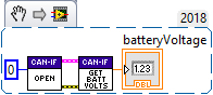
Confirm output matches Self-test Snapshot results.
Bring Up: CANCoder
Magnet Placement
Using the CANCoder User’s Guide, verify that magnet placement is correct for the CANCoder.
Phoenix Tuner
Open Phoenix tuner and use the Self-test Snapshot feature to confirm values. By default, the position value is in units of degrees.
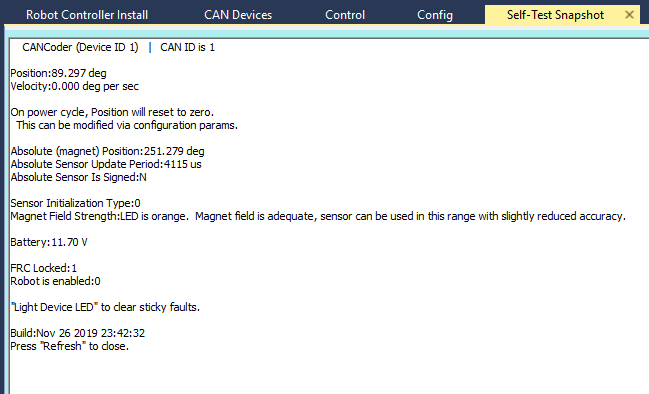
Choose Sensor Direction
Choose which direction of the sensor is positive using the “Sensor Direction” config setting.
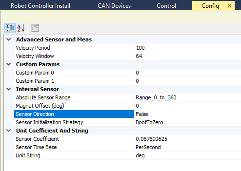
By default, positive direction is counter-clockwise rotation of the magnet when looking at the magnet side of the CANCoder.
Use the self-test snapshot to confirm the sensor value changes as expected for the chosen direction.
Choose Sensor Boot-Initialization Strategy
Select whether the CANCoder position should initialize to 0 or initialize to the absolute position measurement.
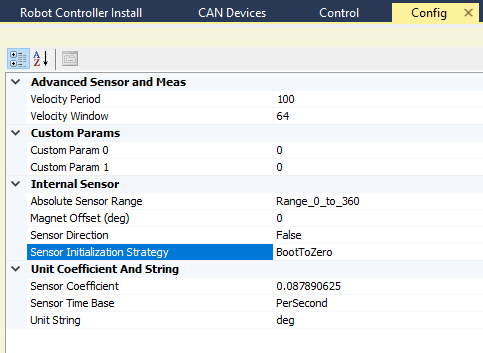
Choose Absolute Sensor Range
Select whether the absolute position value should range from 0 degrees to 360 degrees or -180 to +180.
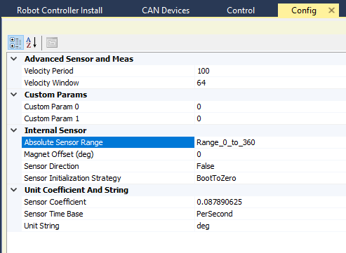
Choose Absolute Sensor Offset
Choose an offset for the 0 point of the absolute measurement.
By default, this 0 point is when the magnet’s north aligns with the LED on the CANCoder.
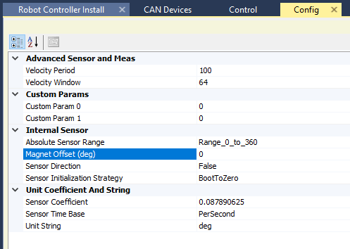
Note
For mechanisms with a fixed range of motion, the offset should be set so that the discontinuity of the absolute measurement (ie, the rollover from 360 -> 0 or 180 -> -180) does not occur in the mechanism’s range of motion.
CANCoder API
Create a CANCoder object in your robot project and poll the position value.
import com.ctre.phoenix.sensors.CANCoder;
public class Robot extends TimedRobot {

CANCoder _coder = new CANCoder(1);
int _loopCount = 0;

public void teleopPeriodic() {
        if(_loopCount++ > 10)
        {
            _loopCount = 0;
            int degrees = _coder.getPosition();
            System.out.println("CANCoder position is: " + degrees);
        }
    }
Confirm that the output matches the self-test snapshot results.
Bring Up: Talon FX/SRX and Victor SPX
At this point all Talon and Victors should appear in Tuner with up to date firmware. The next goal is to drive the motor controller manually. This is done to confirm/test:
Motor and motor wiring
Transmission/Linkage
Mechanism design
Motor Controller drive (both directions)
Motor Controller sensor during motion
Note
Talon FX/SRX and Victor SPX can be used with PWM or CAN bus. This document covers the CAN bus use-case.
Before we enable the motor controller, first check or reset the configs in the next section.
Factory Default Motor Controller
Open the config view to see all persistent settings in the motor controller. This can be done in the config tab (Windows => Config).
Select the Victor or Talon in the center-top dropdown. This will reveal all persistent config settings.
Press Factory Default to default the motor controller settings so that it has predicable behavior.
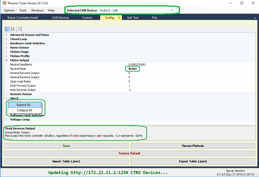
Tip
Right-click anywhere in the property inspector and select Collapse-all to collapse each config group.
Tip
Other configs can be set in this view for testing purposes. For example, you may want to restrict the maximum output for testing via the Peak output settings under “Motor Output”.
Tip
When a setting is modified, it is set to bold to indicate that it is pending. The bold state will clear after you Save.
Tip
If changing a config live in the robot controller, use the Refresh/Revert button to confirm setting in Tuner.
Note
CTRE devices can be factory defaulted via the API, and thru the B/C mechanical button.
Note
Neutral Mode will not change during factory default as it is stored separately from the other persistent configs.
Configuration
Configurable settings are persistent settings that can be modified via the Phoenix API (from robot code) or via Tuner (Config tab). They can also be factory defaulted using either method.
Configs are modified via the config* routines and LabVIEW Vis. There are two general methods for robust operation of a robot. Additionally you can modify the configs via Tuner.
Method 1 – Use the configAll API
Starting with 2019, there is a single routine/VI for setting all of the configs in a motor controller. This ensures that your application does not need to be aware of every single config in order to reliably configure a fresh or unknown motor controller.
This is the recommend API for new robot projects.
Tip
Config structure/object defaults all values to their factory defaults. This means generally you only need to change the settings you care about.
Tip
When using C++/Java, leverage the IntelliSense (Auto-complete) features of the IDE to quickly discover the config settings you need.
Method 2 – Factory Default and config* routines
Phoenix provides individual config* routines for each config setting. Although this is adequate when the number of configs was small, this can be difficult to manage due to the many features/configs in the CTRE motor controllers.
If using individual config routines, we recommend first calling the configFactoryDefault routine/VI to ensure motor controller is restored to a known state, thus allowing you to only config the settings that you intend to change.
This is recommend for legacy applications to avoid porting effort.
Method 3 – Use Tuner
Tuner can be used to get/set/export/import the configs.
However, it is highly recommended to ultimately set them via the software API. This way, in the event a device is replaced, you can rely on your software to properly configured the new device, without having to remember to use Tuner to apply the correct values.
A general recommendation is to:
Configure all devices during robot-bootup using the API,
Use Tuner to dial values quickly during testing/calibration.
Export the settings so they are not lost.
Update your software config values so that Tuner is no longer necessary.
Control Signals
The majority of the behavior in the Talon/Victor is controlled via configs, however there is a small number of control signals that are controlled via the API.
This list includes:
Current Limit Enable (though the thresholds are configs)
Voltage Compensation Enable (though the nominal voltage is a config)
Control Mode and Target/Output demand (percent, position, velocity, etc.)
Invert direction and sensor phase
Closed-loop slot selection [0,3] for primary and aux PID loops.
Neutral mode override (convenient to temporarily override configs)
Limit switch override (convenient to temporarily override configs)
Soft Limit override (convenient to temporarily override configs)
Status Frame Periods
These control signals do not require periodic calls to ensure they “stick”. All of the above signals are automatically restored even after motor controller is power cycled during use except for Status Frame Periods, which can be manually restore by polling for device resets via hasResetOccurred().
Note
WPI motor safety features may require periodic calls to Set() if team software has chosen to enable it.
Note
The override control signals are useful for applications that require temporarily disabling or changing behavior. For example, overriding-disable the soft limits while performing a self-calibration routine to tare sensors, then restoring soft limits for robot operation.
Note
The routines to manipulate control signals are not prefixed with config* to highlight that they are not configs
Test Drive with Tuner
Navigate to the control tab to view the control interface. Notice there are two enable/disable buttons. One is for non-FRC style robot-enable (alternative to the Driver Station enable), and one is for Motor Controller Control-Enable.
Press on the question mark next to the robot disabled/enabled button.
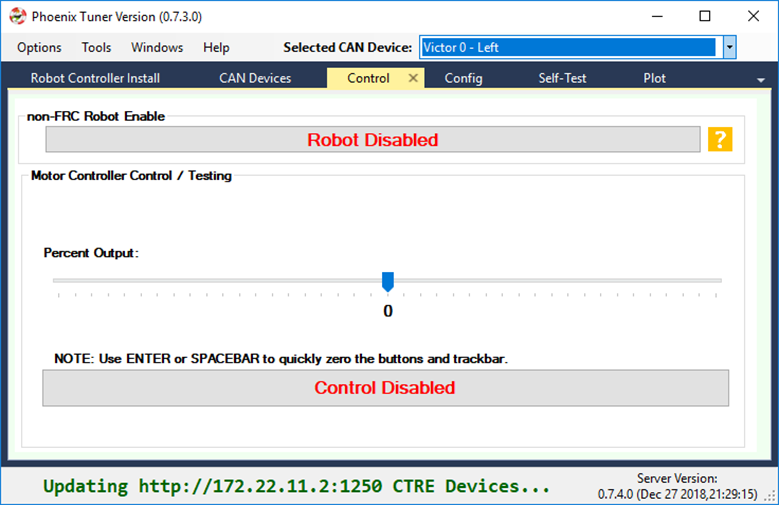
This will reveal the full explanation of how to safely enable your motor controller. Follow the appropriate instructions depending on if you want to use Driver Station for your robot-enable.

Setting up non-FRC Control
In order to enable without the Driver Station you must use a non-roboRIO platform and disconnect the roboRIO from the CAN bus.
With an FRC roboRIO, you must always use the Driver Station to enable.
Confirm FRC Unlock
Self-test Snapshot Motor Controller to confirm device FRCLocked = 0.
If device is FRC Locked (=1), use factory default in the config tab to clear the state. Note that if an FRC roboRIO is on the CAN bus, the motor controller will immediately FRC Lock again.
Note
Use the config export tool if you need to keep your config settings.
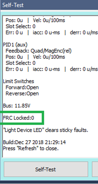
Control tab
Press both Robot Enabled and Control Enabled. At this point you can use the track bar to drive the Victor/Talon.
Note
If you do connect with a roboRIO, the Talon/Victor will FRC Lock again. At which point you must use the driver station to enable, and you no longer need to use the non-FRC Robot enable in Tuner.
Note
Spacebar or enter can be used to clear the control tab and neutral the selected motor controller.
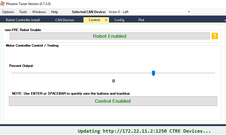
Plot tab
Now open the Plot window. Drive the motor controller while observing the plot. Confirm the blue motor output curve matches LED behavior and trackbar. Confirm motor movement follows expectations.
Note
Press the Plot enable button to effectively pause the plot for review
Note
Use the Zoom buttons to select whether the mouse adjust the Y or X axis.
Note
If using a Victor SPX, current-draw will always read zero (SPX does not have current-measurement features).
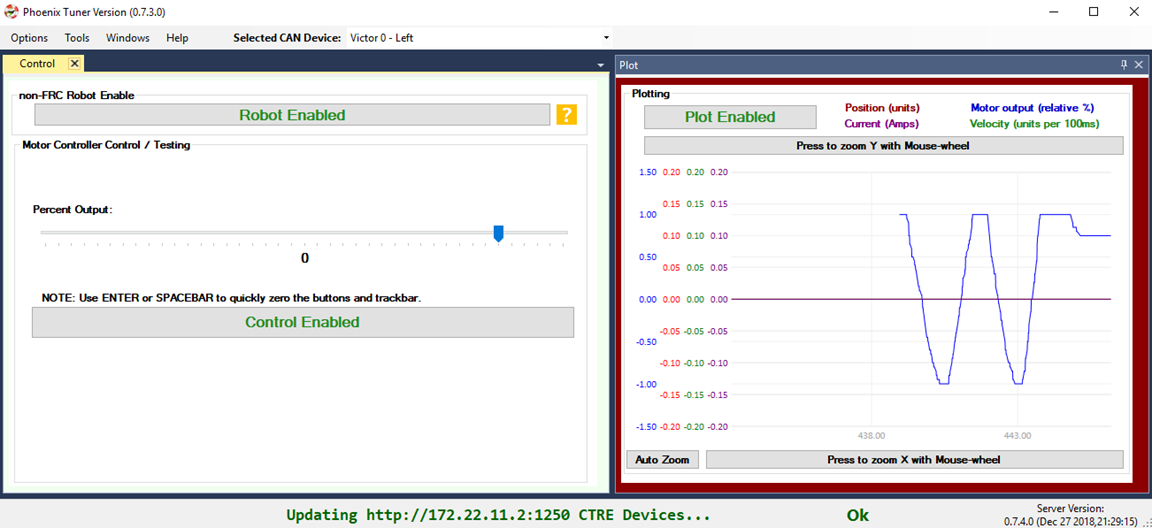
Tip
Plot can be used anytime, regardless of what is commanding the motor controller (FRC or non-FRC).
Test Drive with Robot Controller
Next we will create control software in the roboRIO. Currently this is necessary for more advanced control. This is also required for controlling your robot during competition.
Tip
The latest version of Tuner allows for testing most closed-loop control modes without writing software.
Java: Sample driving code
Below is a simple example that reads the Joystick and drives the Talon
package frc.robot;

import com.ctre.phoenix.motorcontrol.ControlMode;
import com.ctre.phoenix.motorcontrol.can.TalonSRX;

import edu.wpi.first.wpilibj.Joystick;
import edu.wpi.first.wpilibj.TimedRobot;

public class Robot extends TimedRobot {
  TalonSRX _talon0 = new TalonSRX(0); // Change '0' to match device ID in Tuner.  Use VictorSPX for Victor SPXs
  Joystick _joystick = new Joystick(0);

  @Override
  public void teleopPeriodic() {
    double stick = _joystick.getRawAxis(1);
    _talon0.set(ControlMode.PercentOutput, stick);
  }
}
Tip
Image below can be dragged/dropped into LabVIEW editor.
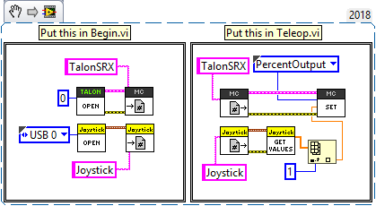
Deploy the project, and confirm success.
Note
WPI’s terminal output may read “Build” successful despite the project was deployed.
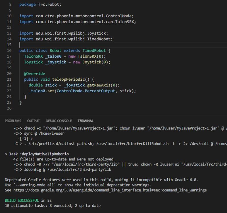
Note
Before you enable the DS, spin the Joystick axis so it reaches the X and Y extremities are reached. USB Gamepads calibrate on-the-fly so if the Gamepad was just inserted into the DS, it likely has not auto detected the max mechanical range of the sticks.
Note
Make sure joystick is detected by the DS before enabling.
Note
getRawAxis may not return a positive value on forward-stick. Confirm this by watching Talon/Victor LED. Green suggests a positive output.
Enable the Driver Station and confirm:
motor drive in both directions using gamepad stick.
motor controller LEDs show green for forward and red for reverse
Disable Driver Station after finished testing.
Note
If the LED is solid orange than use Tuner to determine the cause. Self-test Snapshot will report the current state of the motor controller (do this while troubleshooting). Confirm firmware is up to date.
Open-Loop Features
After some rudimentary testing, you will likely need to configure several open-loop features of the Talon SRX and Victor SPX.
Note
We recommend configuring Inverts and Followers first.
Inverts
To determine the desired invert of our motor controller, we will add two more lines of call. SetInverted is added to decide if motor should spin clockwise or counter clockwise when told to move positive/forward (green LEDs).
We also multiply the joystick so that forward is positive (intuitive). This can be verified by watching the console print in the Driver Station.
package frc.robot;
import com.ctre.phoenix.motorcontrol.*;
import com.ctre.phoenix.motorcontrol.can.*;

import edu.wpi.first.wpilibj.Joystick;
import edu.wpi.first.wpilibj.TimedRobot;

public class Robot extends TimedRobot {
  TalonSRX _talon0 = new TalonSRX(0);
  Joystick _joystick = new Joystick(0);

  @Override
  public void teleopInit() {
    _talon0.setInverted(false); // pick CW versus CCW when motor controller is positive/green
  }

  @Override
  public void teleopPeriodic() {
    double stick = _joystick.getRawAxis(1) * -1; // make forward stick positive
    System.out.println("stick:" + stick);

    _talon0.set(ControlMode.PercentOutput, stick);
  }
}
Tip
Image below can be dragged/dropped into LabVIEW editor.
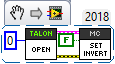
Talon FX Specific Inverts
Talon FX has a new set of inverts that are specific to it, TalonFXInvertType.Clockwise and TalonFXInvertType.CounterClockwise. These new inverts allow the user to know exactly what direction the Falcon 500 will spin. These inverts are from the perspective of looking at the face of the motor.
Below is an image demonstrating the Falcon’s Clockwise rotation:
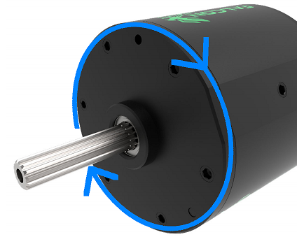
And below is the Falcon’s CounterClockwise rotation:
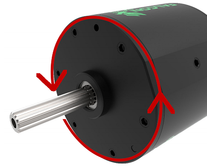
Follower
If a mechanism requires multiple motors, than there are likely multiple motor controllers. The Follower feature of the Talon FX/SRX and Victor SPX is a convenient method to keep two or more motor controller outputs consistent. If you have an external sensor for closed-looping, connect that to the “master” Talon SRX (unless it is a remote sensor such as CANcoder/CANifier/Pigeon).
Below we’ve added a new Victor to follow Talon 0.
Generally, a follower is intended to match the direction of the master, or drive in the opposite direction depending on mechanical orientation. In previous seasons teams would have to update the bool true/false of the follower to match or oppose the master manually.
Starting in 2019, C++/Java users can set the setInverted(InvertType) to instruct the motor controller to either match or oppose the direction of the master instead.
package frc.robot;

import com.ctre.phoenix.motorcontrol.*;
import com.ctre.phoenix.motorcontrol.can.*;

import edu.wpi.first.wpilibj.Joystick;
import edu.wpi.first.wpilibj.TimedRobot;

public class Robot extends TimedRobot {
  TalonSRX _talon0 = new TalonSRX(0);
  VictorSPX _victor0 = new VictorSPX(0);
  Joystick _joystick = new Joystick(0);

  @Override
  public void teleopInit() {
    _victor0.follow(_talon0);

    _talon0.setInverted(false); // pick CW versus CCW when motor controller is positive/green
    _victor0.setInverted(InvertType.FollowMaster); // match whatever talon0 is
    //_victor0.setInverted(InvertType.OpposeMaster); // opposite whatever talon0 is
  }

  @Override
  public void teleopPeriodic() {
    double stick = _joystick.getRawAxis(1) * -1; // make forward stick positive
    System.out.println("stick:" + stick);

    _talon0.set(ControlMode.PercentOutput, stick);
  }
}
Tip
Image below can be dragged/dropped into LabVIEW editor.
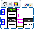
Note
LabVIEW does not support using InvertType to follow master or oppose master
Enable the Driver Station and slowly drive both MCs from neutral. Confirm both LEDs are blinking the same color.
Disable Driver Station when complete.
To confirm motor controllers are truly driving in the same direction, disconnect the master motor controller from its motor.
Enable the Driver Station and confirm follower motor direction matches previously measured master motor direction.
Disable Driver Station when complete.
Open Tuner and select the master motor controller.
Open plot tab and enable plotter while driving motor controller
Confirm current plot is appropriate. If motors are free-spinning, then current should be near 0 if motor output is constant. When testing drive train, the robot should be rested on a crate/tote to ensure all wheels spin freely.
Select follower motor in Tuner, and confirm current via plot.
Note
Follower mode can be canceled by calling set() with any other control mode, or calling neutralOutput().
Note
Calling follow() in the periodic loop is not required, but also does not affect anything in a negative way.
Controlling Followers with Phoenix Tuner
Oftentimes you want to test/tune a mechanism with a master motor controller and one or more followers. This can be accomplished with Phoenix Tuner in the same manner as if there was only one controller, as long as the followers are configured to follow the master. This means you cannot run a temporary diagnostic server to control multiple motor controllers at the same time.
It is imperative to make sure the followers are configured correctly by following the steps above. The followers will use their settings from the user application, even when following a master controlled by Tuner.
Tip
This is the recommended way to tune two or more mechanically linked motors. By having one motor controller as a master, it will handle the PID closed looping while all followers match the applied output of the master.
Neutral Mode
You may note that when the motor output transitions to neutral, the motors free spin (coast) in the last direction they were driven. If the Talon/Victor is set to “coast” neutral mode, then this is expected. The neutral mode can also be set to “brake” to electrically common the motor leads during neutral, causing a deceleration that combats the spinning motor motion.
Tip
You can use Talon FX’s ConfigStatorCurrentLimit method to dial in how strong the brake is.
Note
SetNeutralMode() can be used change the neutral mode on the fly.
TalonSRX talon = new TalonSRX(0);
talon.setNeutralMode(NeutralMode.Brake);
Tip
Image below can be dragged/dropped into LabVIEW editor.
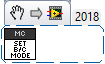
Follower motor controllers have separate neutral modes than their masters, so you must choose both. Additionally, you may want to mix your neutral modes to achieve a partial electric brake when using multiple motors.
Neutral Deadband
A device’s neutral deadband is the region where the controller demotes its output to neutral. This can be configured in your robot code, with a default value of 0.04 or 4%, and a range of [0.001, 0.25] or [0.1%, 25%].
_talon.configNeutralDeadband(0.001); /* Configures _talon to use a neutral deadband of 0.1% */
Talon FX has 3 different deadband strategies based on its state. They are Simple, Continuous, and None.
A Simple deadband will demote any requested output within the region to neutral, and otherwise uphold the requested demand. An example of this is with a configured deadband of 4% and a requested output of 4% will be 0%, 5% output will be 5%, and 100% will be 100%. This is used in the majority of circumstances so it’s obvious that the requested output is the applied output outside the neutral deadband.
A Continuous deadband is similar to a simple deadband in that it demotes any requested output within the region to neutral, but outside the region it will scale the applied output so it’s continuous out of the deadband thresholds. This allows for a smooth transition out of neutral. With a 4% deadband, a requested output of 4% will result in an applied output of 0%, requesting 5% will bring it to 1%, and 100% will be 100%.
A None deadband will not uphold the deadband whatsoever. A deadband of 4% with 4% requested output will apply 4%, 5% is 5%, and 100% is 100%. This is used only in follower mode so you don’t have to configure the deadband of your followers, only of the master.
The below graph highlights this, exaggerrating the effect to make it obvious.
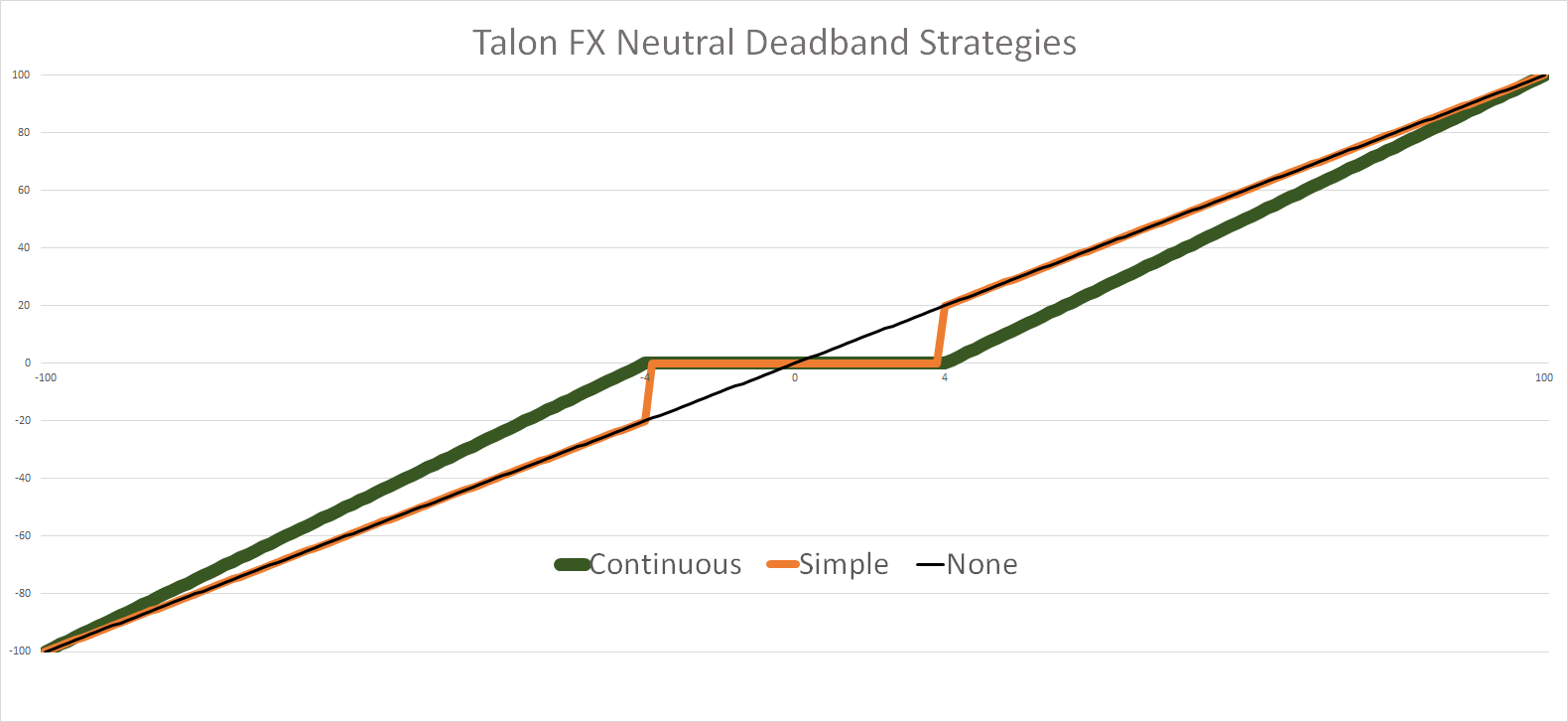
The below table details what neutral deadband strategy the Talon FX uses under the various states.
Mode |
Condition |
Deadband Type |
|---|---|---|
PWM Control |
X |
Continuous |
Percent Output |
Voltage Compensation Disabled |
Continuous |
Percent Output |
Voltage Compensation Enabled |
Simple |
Closed Loop |
X |
Simple |
Auxiliary Follower |
X |
Simple |
Follower |
X |
None |
Ramping
The motor controller can be set to honor a ramp rate to prevent instantaneous changes in throttle. This ramp rate is in effect regardless of which mode is selected (throttle, follower, or closed-loop).
Ramp can be set in time from neutral to full using configOpenLoopRampRate().
Note
configClosedLoopRampRate() can be used to select the ramp during closed-loop (sensor) operations.
Note
The slowest ramp possible is ten seconds (from neutral to full), though this is quite excessive.
TalonSRX talon = new TalonSRX(0);
talon.configOpenloopRamp(0.5); // 0.5 seconds from neutral to full output (during open-loop control)
talon.configClosedloopRamp(0); // 0 disables ramping (during closed-loop control)
Tip
Images below can be dragged/dropped into LabVIEW editor.
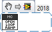
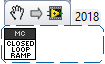
Peak/Nominal Outputs
Often a mechanism may not require full motor output. The application can cap the output via the peak forward and reverse config setting (through Tuner or API).
Additionally, the nominal outputs can be selected to ensure that any non-zero requested motor output gets promoted to a minimum output. For example, if the nominal forward is set to +0.10 (+10%), then any motor request within (0%, +10%) will be promoted to +10% assuming request is beyond the neutral dead band. This is useful for mechanisms that require a minimum output for movement, and can be used as a simpler alternative to the kI (integral) component of closed-looping in some circumstances.
Voltage Compensation
Talon FX/SRX and Victor SPX can be configured to adjust their outputs in response to the battery voltage measurement (in all control modes). Use the voltage compensation saturation config to determine what voltage represents 100% output.
Then enable the voltage compensation using enableVoltageCompensation().
Advanced users can adjust the Voltage Measurement Filter to make the compensation more or less responsive by increasing or decreasing the filter. This is available via API and via Tuner
TalonSRX talon = new TalonSRX(0);
talon.configVoltageCompSaturation(11); // "full output" will now scale to 11 Volts for all control modes when enabled.
talon.enableVoltageCompensation(true); // turn on/off feature
Tip
Image below can be dragged/dropped into LabVIEW editor.
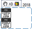
Current Limit
Legacy API
Talon FX/SRX supports current limiting in all control modes.
The limiting is characterized by three configs:
Peak Current (Amperes), threshold that must be exceeded before limiting occurs.
Peak Time (milliseconds), thresholds that must be exceed before limiting occurs
Continuous Current (Amperes), maximum allowable current after limiting occurs.
TalonSRX talon = new TalonSRX(0);
talon.configPeakCurrentLimit(30); // don't activate current limit until current exceeds 30 A ...
talon.configPeakCurrentDuration(100); // ... for at least 100 ms
talon.configContinuousCurrentLimit(20); // once current-limiting is actived, hold at 20A
talon.enableCurrentLimit(true);
Tip
Image below can be dragged/dropped into LabVIEW editor.
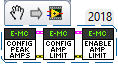
If enabled, Talon SRX will monitor the supply-current looking for a conditions where current has exceeded the Peak Current for at least Peak Time. If detected, output is reduced until current measurement is at or under Continuous Current.
Note
If Peak current limit is set less than continuous limit, peak current limit will be set equal to continuous current limit.
Once limiting is active, current limiting will deactivate if motor controller can apply the requested motor output and still measure current-draw under the Continuous Current Limit.
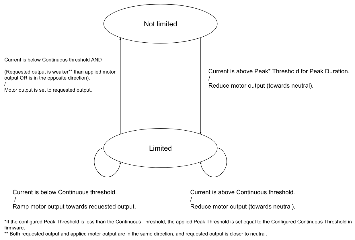
After setting the three configurations, current limiting must be enabled via enableCurrentLimit() or LabVIEW VI.
Note
Use Self-test Snapshot to confirm if Current Limiting is occurring
Note
If peak limit is less than continuous limit, peak is set equal to continuous
Note
If you only want continuous limiting, you should set peak limit to 0
New API in 2020
Talon FX supports both stator(output) current limiting and supply(input) current limiting.
Supply current is current that’s being drawn at the input bus voltage. Stator current is current that’s being drawn by the motor.
Supply limiting (supported by Talon SRX and FX) is useful for preventing breakers from tripping in the PDP.
Stator limiting (supported by Talon FX) is useful for limiting acceleration/heat.
The new API leverages the configSupplyCurrentLimit and configStatorCurrentLimit routines. The configs are similar to the existing legacy API, but the configs have been renamed to better communicate the design intent. For example, instead of configPeakCurrentLimit, the setting is referred to as triggerThresholdCurrent.
/**
  * Configure the current limits that will be used
  * Stator Current is the current that passes through the motor stators.
  *  Use stator current limits to limit rotor acceleration/heat production
  * Supply Current is the current that passes into the controller from the supply
  *  Use supply current limits to prevent breakers from tripping
  *
  *                                                               enabled | Limit(amp) | Trigger Threshold(amp) | Trigger Threshold Time(s)  */
  _tal.configStatorCurrentLimit(new StatorCurrentLimitConfiguration(true,      20,                25,                1.0));
  _tal.configSupplyCurrentLimit(new SupplyCurrentLimitConfiguration(true,      10,                15,                0.5));
An example of this is available on our Github Examples repository
Reading status signals
The Talon FX/SRX and Victor SPX transmit most of their status signals periodically, i.e. in an unsolicited fashion. This improves bus efficiency by removing the need for “request” frames, and guarantees that the signals necessary for the wide range of use cases they support are available.
These signals are available in API regardless of what control mode the Talon SRX is in. Additionally the signals can be polled using Phoenix Tuner using the Self-test Snapshot button.
Included in the list of signals are:
Quadrature Encoder Position, Velocity, Index Rise Count, Pin States (A, B, Index)
Analog-In Position, Analog-In Velocity, 10bit ADC Value,
Battery Voltage, Current, Temperature
Fault states, sticky fault states,
Limit switch pin states
Applied Throttle (duty cycle) regardless of control mode.
Applied Control mode: Voltage % (duty-cycle), Position/Velocity closed-loop, or follower.
Brake State (coast vs brake)
Closed-Loop Error, the difference between closed-loop set point and actual position/velocity.
Sensor Position and Velocity, the signed output of the selected Feedback device (robot must select a Feedback device, or rely on default setting of Quadrature Encoder).
Integrated Sensor (Talon FX).
Magnet position and strength (CANCoder).
Tip
In LabVIEW, these signals can all be obtained from the “Get” VI from the motor controller’s sub-pallette. Choose the type of signals desired from the VI’s drop-down menu.
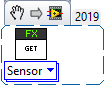
Limit Switches
Talon SRX and Victor SPX have limit features that will auto-neutral the motor output if a limit switch activates. Talon SRX in particular can automatically do this when limit switches are connected via the Gadgeteer feedback port.
An “out of the box” Talon will default with the limit switch setting of “Normally Open” for both forward and reverse. This means that motor drive is allowed when a limit switch input is not closed (i.e. not connected to ground). When a limit switch input is closed (is connected to ground) the Talon SRX will disable motor drive and individually blink both LEDs red in the direction of the fault (red blink pattern will move towards the M+/white wire for positive limit fault, and towards M-/green wire for negative limit fault).
Since an “out of the box” Talon will likely not be connected to limit switches (at least not initially) and because limit switch inputs are internally pulled high (i.e. the switch is open), the limit switch feature is default to “normally open”. This ensures an “out of the box” Talon will drive even if no limit switches are connected.
For more information on Limit Switch wiring/setup, see the Talon SRX User’s Guide.

Limit switch features can be disabled or changed to “Normally Closed” in Tuner and in API.
Note
When the source is set to Gadgeteer, the “Device ID” field is ignored. This config is used for remote limit switches (see next section).
Confirm the limit switches are functional by applying a weak positive motor output while tripping the forward limit switch.
Note
The motor does not have to be physically connected to the motor-controller if tester can artificially assert physical limit switch.
/* Configured forward and reverse limit switch of Talon to be from a feedback connector and be normally open */
Hardware.leftTalonMaster.configForwardLimitSwitchSource(LimitSwitchSource.FeedbackConnector, LimitSwitchNormal.NormallyOpen, 0);
Hardware.leftTalonMaster.configReverseLimitSwitchSource(LimitSwitchSource.FeedbackConnector, LimitSwitchNormal.NormallyOpen, 0);
Limit Switch Override Enable
The enable state of the limit switches can be overridden in software. This can be called at any time to enable or disable both limit switches.
Generally you should call this instead of a config if you want to dynamically change whether you are using the limit switch or not inside a loop. This value is not persistent across power cycles.
/* Limit switches are forced disabled on Talon and forced enabled on Victor */
Hardware.leftTalonMaster.overrideLimitSwitchesEnable(false);
Hardware.rightVictorMaster.overrideLimitSwitchesEnable(true);;
Limit Switch As Digital Inputs
Limit switches can also be treated as digital inputs. This is done in Java/C++ by using the isFwdLimitSwitchClosed & isRevLimitSwitchClosed method.
_talon.getSensorCollection().isFwdLimitSwitchClosed();
_talon.getSensorCollection().isRevLimitSwitchClosed();
Note
The sensor being closed returns true in all cases, and the sensor being open returns false in all cases, regardless of normally open/normally closed setting. This ensures there is no ambiguity in the function name.
Remote Limit Switches
A Talon SRX or Victor SPX can use a remote sensor as the limit switch (such as another Talon SRX or CANifier).
Change the Limit Forward/Reverse Source to Remote Talon or Remote CANifier. Then config the Limit Forward/Reverse Device ID for the remote Talon or CANifier.
/* Configured forward and reverse limit switch of a Victor to be from a Remote Talon SRX with the ID of 3 and normally closed */
Hardware.rightVictorMaster.configForwardLimitSwitchSource(RemoteLimitSwitchSource.RemoteTalonSRX, LimitSwitchNormal.NormallyClosed, 3, 0);
Hardware.rightVictorMaster.configReverseLimitSwitchSource(RemoteLimitSwitchSource.RemoteTalonSRX, LimitSwitchNormal.NormallyClosed, 3, 0);
Use Self-test Snapshot on the motor-driving motor controller to confirm limit switches are interpreted correctly. If they are not correct, then Self-test Snapshot the remote device to determine the issue.
Soft Limits
Soft limits can be used to disable motor drive when the “Sensor Position” is outside of a specified range. Forward throttle will be disabled if the “Sensor Position” is greater than the Forward Soft Limit. Reverse throttle will be disabled if the “Sensor Position” is less than the Reverse Soft Limit. The respective Soft Limit Enable must be enabled for this feature to take effect.
/* Talon configured to have soft limits 10000 native units in either direction and enabled */
rightMaster.configForwardSoftLimitThreshold(10000, 0);
rightMaster.configReverseSoftLimitThreshold(-10000, 0);
rightMaster.configForwardSoftLimitEnable(true, 0);
rightMaster.configReverseSoftLimitEnable(true, 0);
The settings can be set and confirmed in Phoenix Tuner
Bring Up: Talon FX/SRX Sensors
This section is dedicated to validating any rotary sensor attached to the Talon SRX and the integrated sensor on the Talon FX. Generally attaching a sensor is necessary for:
Close-Loop control modes (Position, MotionMagic, Velocity, MotionProfile)
Soft limits (auto neutral motor if out of range)
Sensor Options
Many feedback interfaces are supported. The complete list is below.
Talon FX Integrated Sensor
The Talon FX has a sensor integrated into the controller. This is necessary for the brushless commutation and allows the user to use the Talon FX with a high resolution sensor without attaching any extra hardware.
In order to verify the Integrated Sensor is working, select the Talon FX in the dropdown.

And take a self-test snapshot of the Talon FX. Focus on the integrated sensor section of the snapshot and verify that rotating the shaft results in a change of position.
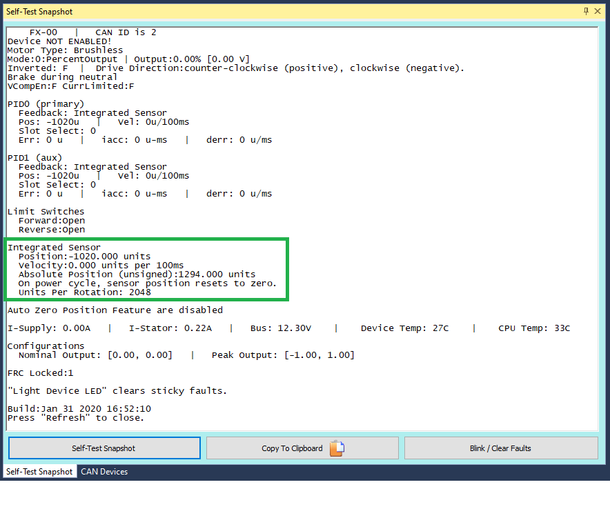
CANCoder
CANCoder is a great sensor to use for applications that require an absolute measurement of a mechanism or would otherwise require a long wire run back to a Talon SRX, CANifier, RIO, etc. If you are using a CANCoder, look at the Bring Up: CANCoder document.
Talon SRX External Ribbon Cabled Sensors
There are many external sensors that are compatible with the Talon SRX in order to utilize its closed-loop functionality or read inside your robot code.
Quadrature
The Talon directly supports quadrature sensors. The decoding is done in 4x mode (every edge on A and B are counted). This is available via the Gadgeteer feedback port.
Tip
Quadrature resets to 0 on power boot.
To verify your quadrature sensor is properly connected to the Talon SRX, select it in the dropdown and take a self-test snapshot of the Talon. Notice the Quadrature section displays all the relevant information about the quadrature sensor.
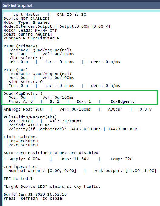
Move the mechanism and take another self test. The position should have changed. If it didn’t, there’s an issue between the sensor and the Talon SRX.
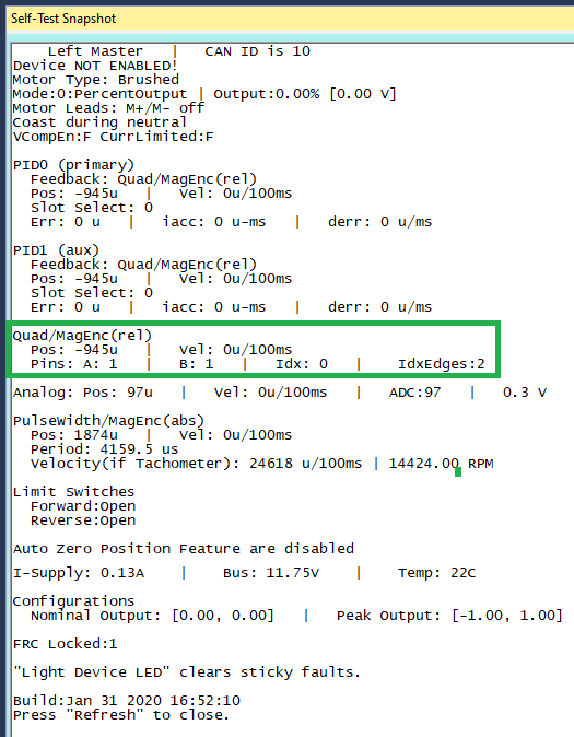
Analog (Potentiometer or Encoder)
Analog feedback sensors are sensors that provide a variable voltage to represent position. Some devices (such as the MA3 US Digital encoder) are continuous and wrap around from 3.3V back to 0V. In such cases the overwrap is tracked, and Talon continues counting 1023 => 1024.
This feature can be disabled by setting the config via API or Tuner.

To check that the analog sensor is working, select your Talon in the drop down and take a self-test snapshot. The Analog section of the snapshot displays all relevant information regarding your analog sensor.
Tip
Analog should read ~100 units if floating. If an analog sensor is meant to be in-circuit, recheck sensor signal/power/harness/etc.
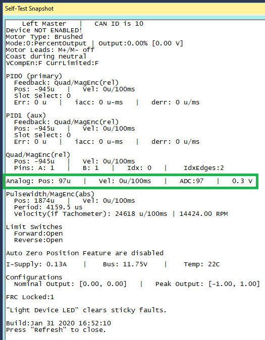
Pulse Width Decoder
For sensors that encode position as a pulse width this mode can be used to decode the position. The pulse width decoder is <1us accurate and the maximum time between edges is 120 ms.
To check that the pulse width sensor is working, select your Talon in the drop down and take a self-test snapshot. The PulseWidth section displays all information regarding the pulse width sensor.
Tip
If using a Talon Tach, focus on the “Velocity (if Tachometer)” value
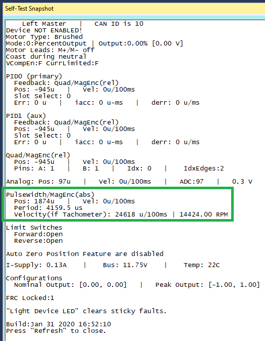
Cross The Road Electronics Magnetic Encoder (Absolute and Relative)
The CTRE Magnetic Encoder is actually two sensor interfaces packaged into one (pulse width and quadrature encoder). Therefore the sensor provides two modes of use: absolute and relative. Each mode provides 4096 units per rotation.
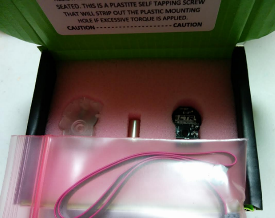
Tip
Inspect the ribbon cable for any frayed or damaged sections.
Tip
Confirm the green LED. When using Versa-Planetary Sensor Slice, orange LED is acceptable.
Warning
When using a contactless sensor on a rolling mechanism (shooter / roller / intake), care should be taken to ensure spinning mechanism is electrically common to the remainder of the robot chassis. Otherwise ESD strikes can occur between mechanism and the contactless sensor (due to its proximity to the mechanism).
The advantage of absolute mode is having a solid reference to where a mechanism is without re-tare-ing or re-zero-ing the robot. The advantage of the relative mode is the faster update rate. However both values can be read/written at the same time. So a combined strategy of seeding the relative position based on the absolute position can be used to benefit from the higher sampling rate of the relative mode and still have an absolute sensor position.
Parameter |
Absolute Mode |
Relative Mode |
|---|---|---|
Update rate (period) |
4 ms |
100 us |
Max RPM |
7,500 RPM |
15,000 RPM |
Accuracy |
12 bits (4096 units per rotation) |
12 bits (4096 units per rotation) |
Software API |
Select Pulse Width |
Select Quadrature |
In circumstances where the absolute pulse width wraps from one extremity to the other (due to overflow), the Talon continues counting 4095 => 4096.
This feature can be disabled by setting the config via API or Tuner.
In order to test that the Mag Encoder is connected properly to the Talon SRX and verify that it is working, you should first select the Talon SRX using the drop down, and take a self-test snapshot of the Talon. The Mag Encoder uses both Quadrature and Pulse Width, so the relevant information for the Mag Encoder will be in both of those sections in the self-test.
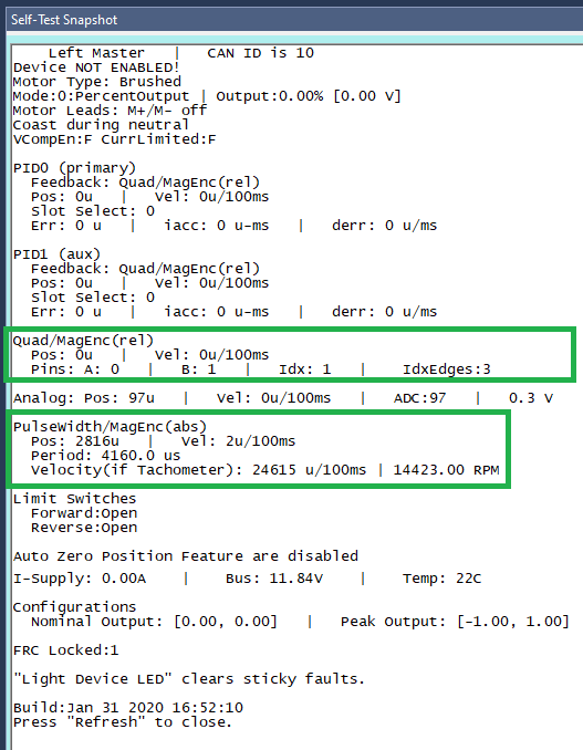
Software-Select Sensor
Once you have decided what sensor you are going to use, you have to select that sensor in the software.
Note
It is imperative that this step is done regardless of if you wish to use the device’s closed-looping features or not.
- This step is done for a number of reasons:
It allows the device to use the selected sensor in its closed looping.
It allows the user to use the getSelected* API
This is updated faster than the sensor-specific gets inside the Sensor Collection.
This obeys the sensor phase that’s been set.
This obeys any sensor coefficient that’s been configured.
Selecting the sensor is done with either Phoenix API or Tuner. In order to select the sensor using Tuner, choose your device in the drop down, access the Config Tab, and select the sensor you are using.
Note
The selected “Feedback Device” defaults to Quadrature Encoder for Talon SRX, None for Victor SPX, and Integrated Sensor for Talon FX.
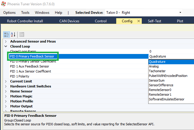
To select it using Phoenix API, call configSelectedFeedbackSensor.
_tal.configSelectedFeedbackSensor(FeedbackDevice.CTRE_MagEncoder_Relative, 0, 10);
Verify the sensor has been selected by taking another self-test snapshot of the device and confirming PID0’s Feedback is the selected sensor
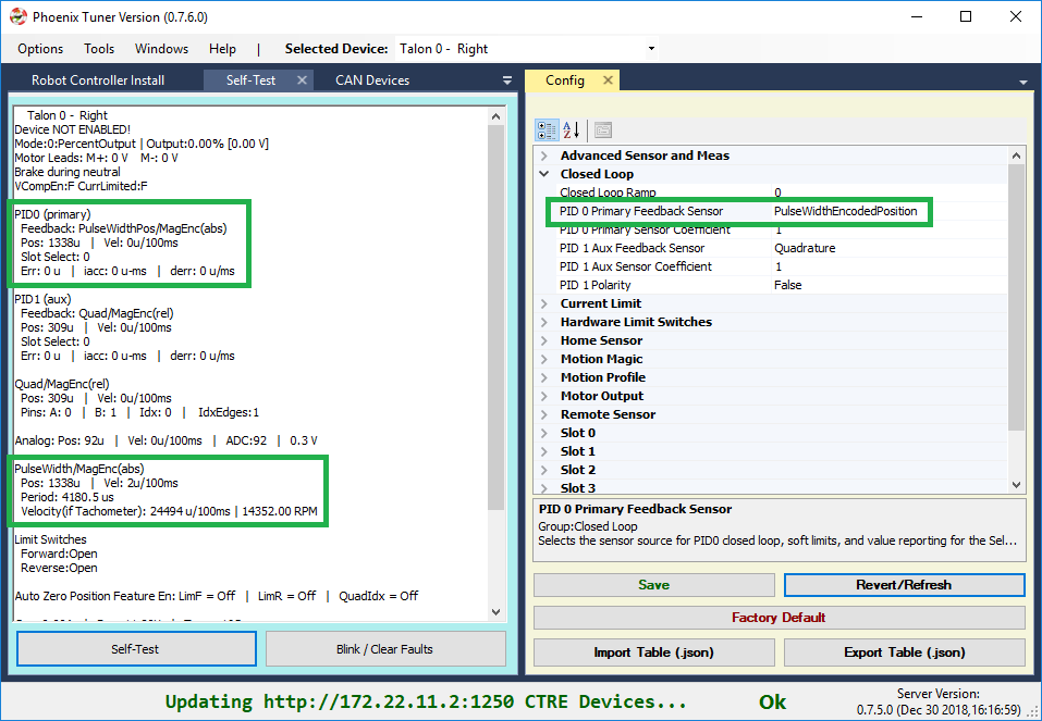
Because the sensor is now “selected”, turn on the plot and hand rotate sensor back and forth. Disable plot to pause after capturing several seconds.
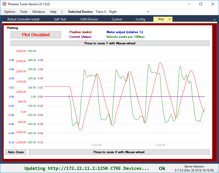
Checks:
Focus the velocity and position curves and look for any discontinuities in the plot.
Shake the sensor harness while hand-turning mechanism.
This is also a good opportunity to confirm the resolution of the sensor.
Sensor Check – With Motor Drive
In this step we will attempt to drive motor while monitoring sensor value. Motor controller can be controlled using Control-tab (see previous relevant section) or controlled from robot application via Phoenix API (see previous relevant section).
Sensor Phase
Sensor phase describes the relationship between the motor output direction (positive vs negative) and sensor velocity (positive vs negative). For soft-limits and closed-loop features to function correctly, the sensor measurement and motor output must be “in-phase”.
Note
Talon FX automatically phases your sensor for you. It will always be correct, provided you use the getSelected* API and have configured the selected feedback type to be integrated sensor.
Measure Sensor Phase
Take another measurement using your preferred control method and check the sensor phase using any of the following methods.
Here we sweep the motor output forward and reverse. Notice that sensor velocity (green) and motor output (blue) are out of phase.
In this capture we use the Self-test Snapshot to observe the motor output and selected (PID0) sensor velocity are signed in opposite directions. Additionally the Talon SRX noticed this and reported a live fault of “Sensor Out of Phase”.
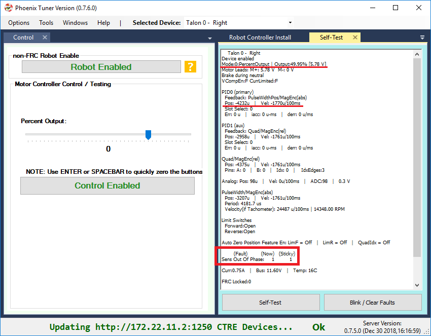
Note
Talon SRX will check sensor direction versus output direction once motor output and velocity exceeds a minimum threshold.
Adjust Sensor Phase
If the sensor is out of phase with the motor drive, you can use any method below to align them:
Recommended: Use setSensorPhase routine/VI to adjust the sensor phase. If already called, toggle the input so that the sensor phase becomes aligned with motor output.
Exchange/flip the green/white motor leads. This is generally not recommended as this makes maintaining motor controller orientation across multiple robots difficult (practice versus competition).
Warning
Do not use setInverted to correct sensor orientation with respect to motor output. setInverted synchronously inverts both signals, ensuring that sensor phase is maintained. This is a feature that allows you to choose what direction is considered positive without breaking closed-looping features.
Confirm Sensor Phase using API
The next test is to control the motor controller using Phoenix API on the robot controller.
This is ultimately how you will leverage the motor controller in competition.
package frc.robot;

import com.ctre.phoenix.motorcontrol.*;
import com.ctre.phoenix.motorcontrol.can.*;
import edu.wpi.first.wpilibj.*;

public class Robot extends TimedRobot {
  TalonSRX _talon = new TalonSRX(0); /* make a Talon */
  Joystick _joystick = new Joystick(0); /* make a joystick */
  Faults _faults = new Faults(); /* temp to fill with latest faults */

  @Override
  public void teleopInit() {
    /* factory default values */
    _talon.configFactoryDefault();

    /*
     * choose whatever you want so "positive" values moves mechanism forward,
     * upwards, outward, etc.
     *
     * Note that you can set this to whatever you want, but this will not fix motor
     * output direction vs sensor direction.
     */
    _talon.setInverted(false);

    /*
     * flip value so that motor output and sensor velocity are the same polarity. Do
     * this before closed-looping
     */
    _talon.setSensorPhase(false); // <<<<<< Adjust this
  }

  @Override
  public void teleopPeriodic() {
    double xSpeed = _joystick.getRawAxis(1) * -1; // make forward stick positive

    /* update motor controller */
    _talon.set(ControlMode.PercentOutput, xSpeed);
    /* check our live faults */
    _talon.getFaults(_faults);
    /* hold down btn1 to print stick values */
    if (_joystick.getRawButton(1)) {
      System.out.println("Sensor Vel:" + _talon.getSelectedSensorVelocity());
      System.out.println("Sensor Pos:" + _talon.getSelectedSensorPosition());
      System.out.println("Out %" + _talon.getMotorOutputPercent());
      System.out.println("Out Of Phase:" + _faults.SensorOutOfPhase);
    }
  }
}
Confirm sensor velocity is in phase with motor output using any of the methods documented above.
Below is an example screenshot of a successfully phased sensor and motor output. Both are negative (good).
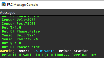
Below is an example screenshot of a successfully phased sensor and motor output. Both are negative (in green).
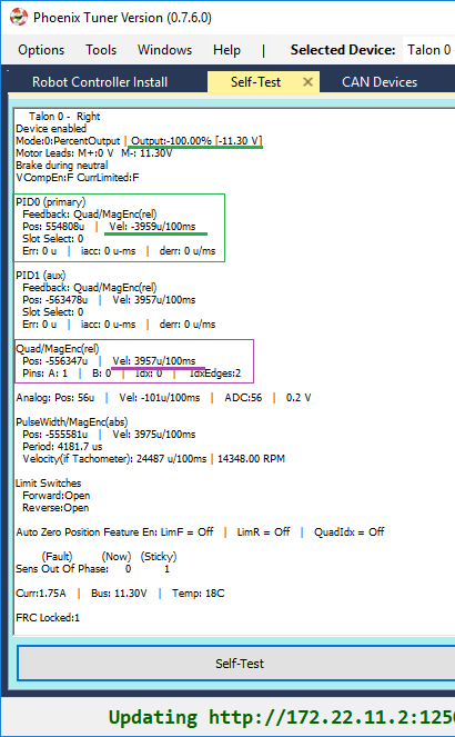
Note
The natural sensor measurement (purple) under Quad is opposite of the Selected sensor value. This is proof-positive that setSensorPhase(true) was used to adjust the sensor phase to better match the motor voltage direction.
What if the sensor Phase is already correct?
The recommendation is to always call setSensorPhase routine/VI. If the phase is naturally correct, then pass false. The reasons to do this are:
During competition, you may find the pit-crew / repair-team wired a replacement motor/harness incorrectly and must resolve this with a “quick software fix”.
During competition, you may find the pit-crew / repair-team wired a replacement sensor/harness incorrectly and must resolve this with a “quick software fix”.
This provides the means of changing the sensor phase to the “wrong value” during hardware-bring up, so you can demonstrate to other team members what an out of phase sensor looks like in your telemetry.
Confirm Sensor Resolution/Velocity
After correcting the sensor phase, the next step is to confirm sensor resolution matches your expectations. This is an important step in sensor validation.
Listed below are the typical sensor resolutions for common sensors. Lookup your sensor type and note the expected resolution. Call this kSensorUnitsPerRotation.
Sensor Resolution
Sensor Type |
Units per rotation |
|---|---|
Quadrature Encoder : US Digital 1024 CPR |
4096 (Talon SRX / CANifer counts every edge) |
CTRE Magnetic Encoder (relative/quadrature) |
4096 |
CTRE Magnetic Encoder (absolute/pulse width) |
4096 |
Talon FX Integrated Sensor |
2048 |
CANCoder |
4096 |
Any pulse width encoded position |
4096 represents 100% duty cycle |
AndyMark CIMcoder |
80 (because 20 pulses => 80 edges) |
Analog |
1024 |
Note
Sensor are typically reported in the raw sensor units to ensure all of the available sensor resolution is utilized. However future releases will allow user to choose how sensor position is interpreted (for example: degrees, radians, inches, legacy raw units, etc.). Users can review the CANCoder API as a reference to how this will work.
Lookup the kMaxRPM of your motor. This will be advertised as the free-speed or max-velocity of your motor.
Determine if your mechanism has a gear-ratio between the motor and your sensor. Typically this is a reduction, meaning that there are several motor rotations per single sensor rotation. Call this kGearRatio.
Calculate the expect peak sensor velocity (sensor units per 100ms) as:
(kMaxRPM / 600) * (kSensorUnitsPerRotation / kGearRatio)
Knowing the maximum possible sensor velocity, compare this against the sensor velocity report in any of the following:
Self-test Snapshot under selected sensor (PID0).
getSelectedSensorVelocity() API
Tuner plotter sensor velocity
You will likely find your ideal value is greater than your measured value due to load. In the case of testing a drive train, it is recommend to place robot on a tote/crate so that wheels can spin free.
If your mechanism does not allow for full motor output due to its design, choose a slower duty cycle and scale by the expected velocity.
Setting Sensor Position
Depending on the sensor selected, the user can modify the “Sensor Position”. This is particularly useful when using a Quadrature Encoder (or any relative sensor) which needs to be “zeroed” or “home-ed” when the robot is in a known position.
Auto Clear Position using Index Pin Or Limit Switches
In addition to manually changing the sensor position, the Talon SRX supports automatically resetting the Selected Sensor Position to zero whenever a digital edge is detected.
This can be activated via config API or config tab in Tuner.
Clear Pos event can be triggered by:
Falling edge on Forward Limit (pin 4)
Falling edge on Reverse Limit (pin 8)
Rising edge on Quadrature Index (pin 9)
talon.configClearPositionOnLimitF(true, timeoutMs);
talon.configClearPositionOnLimitR(true, timeoutMs);
talon.configClearPositionOnQuadIdx(true, timeoutMs);
Self-test Snapshot can also be used to confirm the enabling of auto zero features.
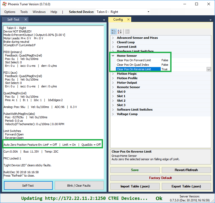
Velocity Measurement Filter
The Talon SRX measures the velocity of all supported sensor types as well as the current position. Every 1ms a velocity sample is measured and inserted into a rolling average.
The velocity sample is measured as the change in position at the time-of-sample versus the position sampled 100ms-prior-to-time-of-sample. The rolling average is sized for 64 samples. Though these settings can be modified, the (100ms, 64 samples) parameters are default.
Changing Velocity Measurement Parameters.
The two configs for the Talon Velocity Measurement are:
Sample Period (Default 100ms)
Rolling Average Window Size (Default 64 samples).
Each can be modified through programming API, and through Tuner.
Note
When the sample period is reduced, the units of the native velocity measurement is still change-in-position-per-100ms. In other words, the measurement is up-scaled to normalize the units. Additionally, a velocity sample is always inserted every 1ms regardless of setting selection.
Note
The Velocity Measurement Sample Period is selected from a fixed list of pre-supported sampling periods [1, 5, 10, 20, 25, 50, 100(default)] milliseconds.
Note
The Velocity Measurement Rolling Average Window is selected from a fixed list of pre-supported sample counts: [1, 2, 4, 8, 16, 32, 64(default)]. If an alternative value is passed into the API, the firmware will truncate to the nearest supported value.
Recommended Procedure
The general recommended procedure is to first set these two parameters to the minimal value of ‘1’ (Measure change in position per 1ms, and no rolling average). Then plot the measured velocity while manually driving the Talon SRX(s) with a joystick/gamepad. Sweep the motor output to cover the expected range that the sensor will be expected to cover.
Unless the sensor velocity is considerably fast (hundreds of sensor units per sampling period) the measurement will be very coarse (visual stair-stepping as the motor output is increased). Increase the sampling period until the measured velocity is sufficiently granular.
At this point the sensor velocity will have minimal stair-stepping (good) but will be quite noisy. Increase the rolling average window until the velocity plot is sufficiently smooth, but still responsive enough to meet the timing requirements of the mechanism.
Next Steps
Additionally if you need to use WPI features such as the drivetrain classes, or motor safety, move on to WPI/NI Software Integration.
Now that you have a reliable sensor, you can setup a closed-loop. This is for use cases where you want your mechanism to automatically move towards a target position, or hold a target velocity. This is covered in Motor Controller Closed Loop.
Bring Up: Remote Sensors
This section provides direction for configuring and validating remote sensor setups. The remote sensor filter feature of the Talon SRX/Victor SPX allows for the processing of sensor values provided from other remote CAN bus devices. In other words, a Talon SRX or Victor SPX can execute closed-loop modes with sensor values sourced by other Talons, CANifiers, or Pigeon IMUs on the same CAN-bus.
This is useful for two general reasons:
Victor SPX does not have a Gadgeteer feedback port, so it must rely on remote sensors for sensor data.
Situations where the sensor is physically located too far from the motor controller for reliable/robust wiring.
As a result, the remote sensor feature enables:
Close-Loop control modes (Position, MotionMagic, Velocity, MotionProfile) when the sensor cannot be directly connected to the motor controller.
Soft limits (auto neutral motor if out of range) when the sensor cannot be directly connected to the motor controller.
Auxiliary PID1 Closed-Loop (differential mechanisms) that requires more than one sensor source (including MotionProfileArc, and all other Closed-Loop control modes).
Note
To use Pigeon IMU as a remote sensor over gadgeteer ribbon cable you must use Pigeon firmware 4.13 or higher. There is a bug that prevents Pigeon from appearing as a remote sensor in some cases over gadgeteer ribbon cable that has been fixed in 4.13
Bring up the sensor on the remote CTRE CAN device
In order to use remote sensors, the sensor must first be validated by the device wired to the sensor. If the sensor is not reliable at the remote device, then it will not function when utilized remotely.
This is done by following the sensor bring up instructions for that particular device type:
Warning
In order for a motor controller to use another Talon sensor as a remote source, that Talon must have the correct sensor type selected. In other words, if Victor X is going to use Talon Y’s analog sensor, Talon Y must have a selected sensor type set to analog.
Warning
Remote sensors accessed by a Talon FX (Falcon 500) must have a CAN ID of 15 or less. See errata Talon FX Remote Filter Device ID Must be 15 or Less for more details.
Note
When PigeonIMU is selected as a remote sensor, the closed loop uses the Pigeon’s native units (8192 units per rotation). This can be changed by configuring a sensor coefficient for the closed loop, see Closed-Loop Configurations.
Filter configuration
Inside Phoenix Tuner select the motor controller that will be utilizing the remote sensor data and go to the config tab. Inside the tab go to the remote sensor portion and expand it, where you will see filter sources and filter device IDs.
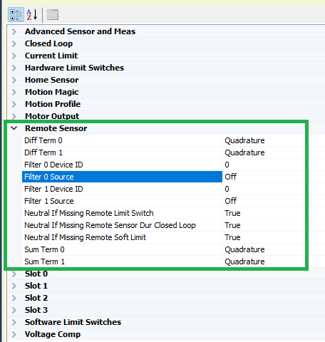
Select the dropdown for filter source 0, and you will see a list of the possible sources of a remote sensor

Select the option that you wish to use, for the purpose of this example we will select a RemoteSRX_SelectedSensor that has configured a quadrature encoder, but any of these will work.
Warning
When selecting a Pigeon IMU data, there are two separate options for Pigeon - one for connection via CAN bus and one for connection to a remote Talon via ribbon cable.
As well as this, select Filter 0 Device ID and set it to the CAN device ID of the remote sensor. Press save, making sure the text goes from bold to non-bold.
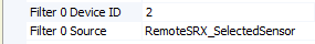
Note
If the filter source is a RemoteGadgeteerPigeon type, the filter Device ID should be the device ID of the remote Talon SRX hosting the Pigeon IMU.
Sensor Check - No Motor Drive
After having the filter configured, it is important to check that it is behaving properly. Under the closed loop section of the configs, configure PID 0 Primary Feedback Sensor to be Remote Sensor 0 and press save.
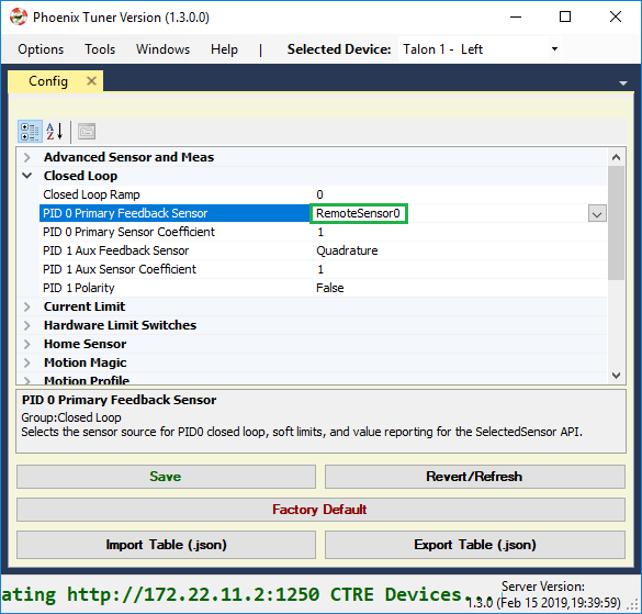
And perform a Self-test Snapshot to make sure the configuration took place.
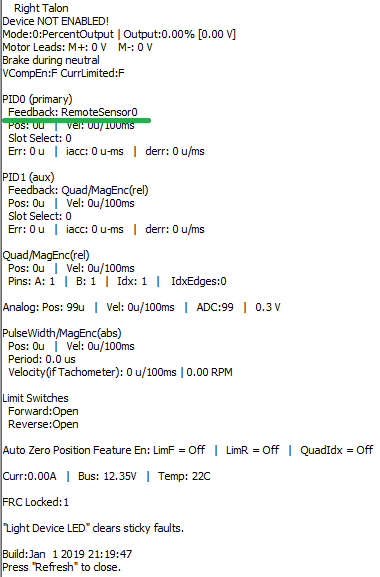
Move the mechanism and perform self test snapshots to check the remote sensor is configured correctly
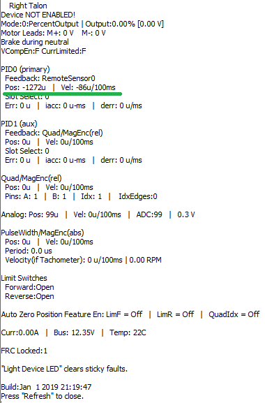
Tip
If something is not behaving correctly, double check the sensor setup for that device. If the sensor setup behaves correctly, the error is somewhere in the filter configuration
Sensor Check - With Motor Drive
See Sensor Check – With Motor Drive for the guide on checking the sensor with motor drive.
Remote Features Check
With the sensor being properly configured, now we can test the remote features. A simple way of testing this is by configuring soft limits and checking to make sure those soft limits are upheld by the controller
First, we configure the soft limits on the motor controller so that they’re enabled and have values for the forward and reverse limits
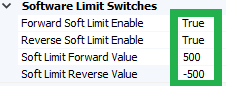
Then, we drive the motor to one of the limits. It will probably overshoot a bit, but the important piece is that the motor controller’s output is neutral after hitting the soft limit, which we can check in the Self-test Snapshot and looking at the faults.
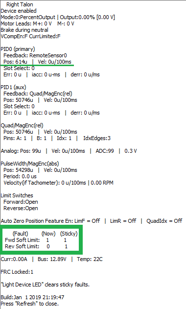
Next Steps
Now that the remote sensor is configured, it can be used for Motor Controller Closed Loop or Bring Up: Differential Sensors.
Bring Up: Differential Sensors
This section is dedicated to validating differential sensors for any CTRE motor controller. Generally a differential sensor is necessary for:
Closed-Loop control modes (Position, MotionMagic, Velocity, MotionProfile) when the mechanism has more than one sensor attached.
Auxiliary Closed-Loop control modes (MotionProfileArc, and all other Closed-Loop control modes) for mechanisms that require a differential component (Such as an elevator where the two sides are not linked mechanically, or a drive train).
Bring up Sensors as Remote/Local sensors
In order to use differential sensors, you must bring up all relevant sensors on their local controller devices.
See relevant BringUp sections below:
After each sensor is brought up on its local device, all remote sensors should be configured as a remote filter on the master device. See Bring Up: Remote Sensors.
Configure sensors as Sum/Diff terms
Once the sensors are brought up and checked, we can move on to configuring them as the sum difference (diff) terms.
The sum of two sensors is used primarily to calculate the overall movement of the mechanism. For example, in the case of a differential lift the sum of two sensors is used to calculate the height of the lift.
Tip
When using the sum of two sensors for total movement, you can also set the Feedback Coefficient to 0.5 on order to scale the value back to the original units.
The difference of two sensors, however, is mostly used to calculate the differential portion of the mechanism. For example, for a differential lift the difference represents how level the lift is.
The sum and diff terms will almost always be the same sensors, and will almost always be a local sensor and a remote sensor (or two remote sensors).
/* Below shows setting the member variables of a motor controller Config object.  */
/* Remote Sensor 0 is the other talon's quadrature encoder */
remoteFilter0.remoteSensorSource = RemoteSensorSource::RemoteSensorSource_TalonSRX_SelectedSensor;
remoteFilter0.remoteSensorDeviceID = otherTalon->GetDeviceID();

/* Configure sensor sum to be this quad encoder and the other talon's encoder */
sum0Term = FeedbackDevice::QuadEncoder;
sum1Term = FeedbackDevice::RemoteSensor0;
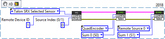
Auxiliary PID Polarity
The Auxiliary PID Polarity flag configures whether the master motor controller uses the addition of the two PID’s and the auxiliary follower uses the subtraction, or if the master uses the subtraction and the auxiliary follower uses the addition.
- Setting this to false will cause the master/follower pair to behave like this:
Master Motor Controller Output = PID[0] + PID[1]
Auxiliary Follower Output = PID[0] - PID[1]
- Setting this to true will cause the master/follower pair to behave like this:
Master Motor Controller Output = PID[0] - PID[1]
Auxiliary Follower Output = PID[0] + PID[1]
Using the differential sensor setup
This is covered in Motor Controller Closed Loop
WPI/NI Software Integration
The stock software frameworks in the FRC control system has several features used by teams. To leverage these features, the C++ /Java Phoenix API has three additional classes:
WPI_TalonFX
WPI_TalonSRX
WPI_VictorSPX
These are wrappers for the Talon FX/SRX and Victor SPX, that provide:
LiveWindow support
Motor Safety features
Compatibility with DriveTrain classes
C++ / Java Drive Train classes
To leverage the Drive Train classes in WPILib:
Create your motor controller objects like normal.
Create the Drive object like normal.
Call setRightSideInverted(false) so that when moving forward, positive output is applied to left and right.
Adjust setInverted() so that motors cause robot to drive straight forward when stick is forward.
package frc.robot;

import com.ctre.phoenix.motorcontrol.can.*;
import edu.wpi.first.wpilibj.*;
import edu.wpi.first.wpilibj.drive.*;

public class Robot extends TimedRobot {
  WPI_TalonSRX _talonL = new WPI_TalonSRX(1);
  WPI_TalonSRX _talonR = new WPI_TalonSRX(0);
  DifferentialDrive _drive = new DifferentialDrive(_talonL, _talonR);
  Joystick _joystick = new Joystick(0);

  @Override
  public void teleopInit() {
    /* factory default values */
    _talonL.configFactoryDefault();
    _talonR.configFactoryDefault();

    /* flip values so robot moves forward when stick-forward/LEDs-green */
    _talonL.setInverted(false); // <<<<<< Adjust this
    _talonR.setInverted(true); // <<<<<< Adjust this

    /*
     * WPI drivetrain classes defaultly assume left and right are opposite. call
     * this so we can apply + to both sides when moving forward. DO NOT CHANGE
     */
    _drive.setRightSideInverted(false);
  }

  @Override
  public void teleopPeriodic() {
    double xSpeed = _joystick.getRawAxis(1) * -1; // make forward stick positive
    double zRotation = _joystick.getRawAxis(2); // WPI Drivetrain uses positive=> right

    _drive.arcadeDrive(xSpeed, zRotation);

    /* hold down btn1 to print stick values */
    if (_joystick.getRawButton(1)) {
      System.out.println("xSpeed:" + xSpeed + "    zRotation:" + zRotation);
    }
  }
}
Tip
It is advantageous to setup Talon / Victors in this fashion so that positive (green) represents forward motion. This makes integrating the other control modes into your drive train simpler.
C++ / Java Motor Safety Feature
The Java classes WPI_TalonFX, WPI_TalonSRX, and WPI_VictorSPX all implement the motor safety interface.
The C++ classes WPI_TalonFX, WPI_TalonSRX, and WPI_VictorSPX do not inherent the motor safety abstract class, but they do implement the exact same routines. This means the same routines can be called on the Phoenix WPI objects.
Motor Controller Closed Loop
Primer on Closed-loop
Talon SRX and Victor SPX supports a variety of closed-loop modes including position closed-loop, velocity closed-loop, Motion Profiling, and Motion Magic. Talon SRX additionally supports current closed-loop.
Note
All closed-loop modes update every 1ms (1000Hz) unless configured otherwise.
Tip
While tuning the closed-loop, use the Tuner configuration tab to quickly change the gains “on the fly”. Once the PID is stable, set the gain values in code so that Talons can be swapped/replaced easily.
Regardless of which closed-loop control mode is used, the following statements apply:
Current limit and voltage compensation selections are honored (just like in open-loop PercentOutput mode)
“Ramping” can be configured using configClosedloopRamp (routine or VI)
All other open-loop features are honored during closed loop (neutral mode, peaks, nominal outputs, etc.).
Closed Loop controller will pull closed-loop gain/setting information from a selected slot. There are four slots to choose from (for gain-scheduling).
PIDF controller takes in target and sensor position measurements in “raw” sensor units. This means a CTRE Mag Encoder will count 4096 units per rotation.
PIDF controller takes in target and sensor velocity measurements in “raw” sensor units per 100ms.
PIDF controller calculates the motor output such that, 1023 is interpreted as “full”. This means a closed loop error of 341 (sensor units) X kP of 3.0 will produce full motor output (1023).
Warning
Although the velocity kF config of the Talon-SRX/Victor-SPX assumes 1023 is full output, do not confuse this with the arbitrary feed-forward parameter of the Set routine/VI, which accepts a value within [-1,+1]
Note
A target goal of 2020 is to normalize the PID controller to interpret sensor using normalized units, and adjusting the PID output such that ‘1’ is interpreted as full. This may be released during the 2020 season. If this is released, the default settings will provide the legacy units, but users will have the ablity to change them, similar to the current CANCoder API.
Below are descriptions for the various control modes.
Closed-Loop Control Modes
Position Closed-Loop Control Mode
The Position Closed-Loop control mode can be used to abruptly servo to and maintain a target position.
A simple strategy for setting up a closed loop is to zero out all Closed-Loop Control Parameters and start with the Proportional Gain.
For example if you want your mechanism to drive 50% throttle when the error is 4096 (one rotation when using CTRE Mag Encoder), then the calculated Proportional Gain would be (0.50 X 10²³) / 4096 = ~0.125.
Tune this until the sensed value is close to the target under typical load. Many prefer to simply double the P-gain until oscillations occur, then reduce accordingly.
If the mechanism accelerates too abruptly, Derivative Gain can be used to smooth the motion. Typically start with 10x to 100x of your current Proportional Gain. If application requires a controlled (smooth) deceleration towards the target, we strongly recommend motion-magic.
If the mechanism never quite reaches the target and increasing Integral Gain is viable, start with 1/100th of the Proportional Gain.
Current Closed-Loop Control Mode
The Talon’s Closed-Loop logic can be used to approach a target current-draw. Target and sampled current is passed into the PIDF controller in milliamperes. However the robot API expresses the target current in amperes.
Note
Current Control Mode is separate from Current Limit.
Tip
A simple strategy for setting up a current-draw closed loop is to zero out all Closed-Loop Control Parameters and start with the Feed-Forward Gain. Tune this until the current-draw is close to the target under typical load. Then start increasing P gain so that the closed-loop will make up for the remaining error. If necessary, reduce Feed-Forward gain and increase P Gain so that the closed-loop will react more strongly to the ClosedLoopError.
Warning
This feature is not available on Victor SPX.
Velocity Closed-Loop Control Mode
The Talon’s Closed-Loop logic can be used to maintain a target velocity. Target and sampled velocity is passed into the equation in native sensor units per 100ms.
Tip
A simple strategy for setting up a closed loop is to zero out all Closed-Loop Control Parameters and start with the Feed-Forward Gain. Tune this until the sensed value is close to the target under typical load. Then start increasing P gain so that the closed-loop will make up for the remaining error. If necessary, reduce Feed-Forward gain and increase P Gain so that the closed-loop will react more strongly to the ClosedLoopError.
Tip
Velocity Closed-Loop tuning is similar to Current Closed-Loop tuning in their use of feed-forward. Begin by measuring the sensor velocity while driving the Talon at a large throttle.
Motion Magic Control Mode
Motion Magic is a control mode for Talon SRX that provides the benefits of Motion Profiling without needing to generate motion profile trajectory points. When using Motion Magic, Talon SRX / Victor SPX will move to a set target position using a motion profile, while honoring the user specified acceleration, maximum velocity (cruise velocity), and optional S-Curve smoothing.
Tip
Motion Magic in firmware >= 4.17 (Talon SRX and Victor SPX) now supports an S-Curve parameter, allowing you to create a continuous velocity profile.
The benefits of this control mode over “simple” PID position closed-looping are:
Control of the mechanism throughout the entire motion (as opposed to racing to the end target position).
Control of the mechanism’s inertia to ensure smooth transitions between set points.
Improved repeatability despite changes in battery voltage.
Improved repeatability despite changes in motor load.
After gain/settings are determined, the robot-application only needs to periodically set the target position.
There is no general requirement to “wait for the profile to finish”, however the robot application can poll the sensor position and determine when the motion is finished if need be.
Motion Magic functions by generating a trapezoidal/S-Curve velocity profile that does not exceed the specified acceleration or cruise velocity. This is done automatically as the Talon SRX / Victor SPX determines on-the-fly when to modify its velocity to accomplish this.
Note
If the remaining sensor distance to travel is small, the velocity may not reach cruise velocity as this would overshoot the target position. This is often referred to as a “triangle profile”.
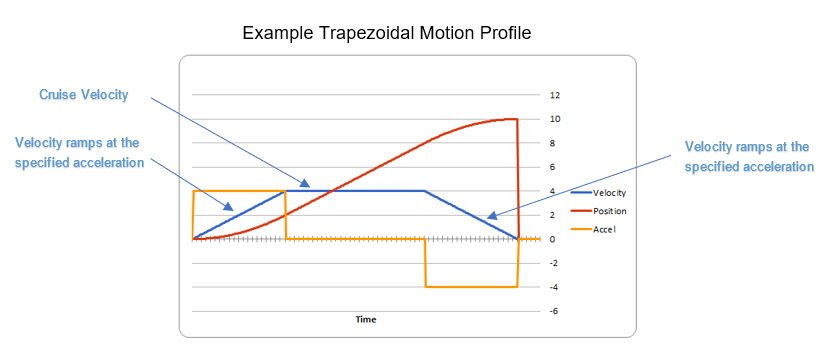
If the S-Curve strength [0,8] is set to a nonzero value, the generated velocity profile is no longer trapezoidal, but instead is continuous (corner points are smoothed).
An S-Curve profile has the following advantages over a trapezoidal profile:
Control over the Jerk of the mechanism.
Reducing oscillation of the mechanism.
Maneuver is more deliberate and reproducible.
Tip
The S-Curve feature, by its nature, will increase the amount of time a movement requires. This can be compensated for by decreasing the configured acceleration value.
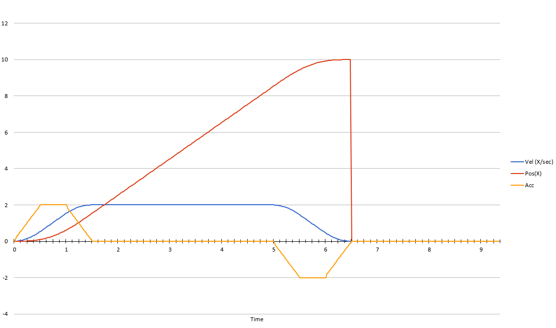
Motion Magic utilizes the same PIDF parameters as Motion Profiling.
Three additional parameters need to be set in the Talon SRX– Acceleration, Cruise Velocity, and Acceleration Smoothing.
The Acceleration parameter controls acceleration and deacceleration rates during the beginning and end of the trapezoidal motion. The Cruise Velocity parameter controls the cruising (peak) velocity of the motion. The Acceleration smoothing parameter controls the “curve” of the velocity, a larger smoothing value will result in greater dampening of the acceleration.
Motion Profile Control Mode
Talon SRX and Victor SPX support other closed-loop modes that allow a “Robot Controller” to specify/select a target value to meet. The target can simply be the percent output motor drive, or a target current-draw. When used with a feedback sensor, the robot controller may also simply set the target position, or velocity to servo/maintain.
However, for advanced motion profiling, the Talon SRX / Victor SPX additionally supports a mode whereby the robot controller can stream a sequence of trajectory points to express an entire motion profile.
Each trajectory point holds the desired velocity, position, arbitrary feedforward, and time duration to honor said point until moving on to the next point. The point also holds targets for both the primary and auxiliary PID controller, allowing for differential control (drivetrain, differential mechanisms).
Alternatively, the trajectory points can be streamed into the motor controller as the motor controller is executing the profile, so long as the robot controller sends the trajectory points faster than the Talon consumes them. This also means that there is no practical limit to how long a profile can be.
Tip
Starting in 2019, the Talon and Victor will linearly interpolate targets between two buffer points every 1ms. This means you can send points with larger time durations, but still have a smooth continuous motion. This features default on.
What is the benefit? Leveraging the Motion Profile Control Mode in the Talon SRX has the following benefits:
Direct control of the mechanism throughout the entire motion (as opposed to a single PID closed-loop which directly servos to the end target position).
Accurate scheduling of the trajectory points that is not affected by the performance of the primary robot controller.
Improved repeatability despite changes in battery voltage.
Improved repeatability despite changes in motor load.
Provides a method to synchronously gain-schedule.
Additionally, this mode could be used to schedule several position servos in advance with precise time outs. For example, one could map out a collection of positions and timeouts, then stream the array to the Talon SRX to execute them.
Motion Profile Arc Control Mode
Motion Profile Arc utilizes the Auxiliary Closed Loop features to profile the motion of not just one degree of freedom, but of two.
In the example of trying to profile the movement of the robot on a field, the primary PID can be used to ensure the robot is a specified distance (sum or average of both sides), and at the same time the Auxiliary PID can be used to ensure the robot is facing the right direction (difference of both sides or heading from a pigeon), allowing the robot to follow a spline.
The benefits of this are the same as for the Motion Profile control mode, and at the same time expands on the possibilities this can be used for.
Auxiliary Closed Loop PID[1]
Along with the above control modes, the Talon SRX / Victor SPX has the ability to run a second PID loop, called the auxiliary PID[1] loop. This is typically used in differential mechanisms where application must maintain two process variables (e.g. sum/average of two sensors, along with the difference or IMU heading).
When used, the motor controller will simultaneously calculate: - PID[0] + PID[1] (this is applied to the motor output) - PID[0] - PID[1] (this is sent to a follower)
Note
The follower Talon / Victor must have a followType of AuxOutput1. Use the follow routine/VI to accomplish this.
Note
The signage of the PID[1] term can be modified allowing the master Talon to subtract the term instead of adding it.
Note
In order to use Auxiliary Closed Loop, a remote sensor will need to have been configured for PID[0] or PID[1]. Look at Bring Up: Remote Sensors to see how to do this
Note
The Control Mode of Auxiliary Closed Loop is always position closed-loop.
Some example setups are provided below, with a step-by-step walkthrough provided after the PID tuning sections. See Auxiliary Closed Loop PID[1] Walkthrough.
Example 1 - Differential Drivetrain
Consider the application of controlling the position of a drive train with Position Control Mode, given an encoder on the left and right side.
PID[0] will use the sum (or average if sensor coefficient is set to 0.5) of the left and right sensor to produce the traveled robot distance. Given a target distance, the PID[0] output will move the robot closer to the target distance. PID[1] will use the difference between the left and right sensor to produce the robot heading. Alternatively the Pigeon IMU can be used to remotely provide this. The PID[1] output will then maintain the robot’s heading throughout the maneuver.
Note
If Velocity control mode is used, the aux PID[1] loop still uses the position value of its respective sensor source. This is convenient for controlling the robot-velocity while maintaining robot-heading.
Note
When using the Motion Magic control mode, the target for PID[1] is smoothed identically to PID[0], and both targets should be reached at approximately the same time.
Note
Sensor difference (and not sum) may represent the distance traveled depending on the signage of the sensors involved.
Example 2 - Lift Mechanism
Consider a lifting mechanism composed of two closed-loops (one for each side) and no mechanical linkage between them. In other words, the left and right side each have a unique motor controller and sensor. The goal in this circumstance is to closed-loop the elevation while keeping the left and right side reasonably synchronized.
This can be accomplished by using the sum of each side as the elevator height, and the difference as the level deviation between the left and right, which must be kept near zero.
Aux PID[1] can then be used to apply a corrective difference component (adding to one side and subtracting from the other) to maintain a synchronous left and right position, while employing Position/Velocity/Motion-Magic to the primary axis of control (the elevator height).
Sensor Preparation
Before invoking any of the closed loop modes, the following must be done:
Complete the sensor bring up procedure to ensure sensor phase and general health.
Record the maximum sensor velocity (position units per 100ms) at 100% motor output.
Calculate an Arbitrary Feed Forward if necessary (gravity compensation, custom system characterization).
Calculating Velocity Feed-Forward (kF) gain if applicable (Velocity Closed Loop, Motion Profile, Motion Magic).
The first two are covered in section “Confirm Sensor Resolution/Velocity”. Calculating feed forward is done in the next section.
Arbitrary Feed Forward
The Arbitrary Feed Forward is a strategy for adding any arbitrary values to the motor output regardless of control mode. It can be used for gravity compensation, custom velocity and acceleration feed forwards, static offsets, and any other term desired.
Note
When setting and tuning closed-loop gains, Arbitrary Feed Forward should be set first, before any other values. The Arbitrary Feed Forward will change the relationship between your closed-loop gains and the output of your system, and thus result in different gains needed for a well-tuned mechanism.
Note
Unlike other closed-loop gains, the Arbitrary Feed Forward is passed in as an additional set() parameter instead of as a persistent configuration parameter. This is because typical use-cases for Arbitrary Feed Forward frequently change the value dynamically.
Warning
Arbitrary Feed Forward and Auxiliary Closed Loop cannot be used simultaneously except when using Motion Profile Arc.
Do I need to use Arbitrary Feed Forward?
We recommend using Arbitrary Feed Forward in any of the following scenarios:
A mechanism affected by gravity (elevator, arm, etc.).
Custom system characterization (such as acceleration feed forward).
Any scenario requiring a static offset.
Note
Units for the arbitrary feedforward term are [-1,+1].
Setting Arbitrary Feed Forward
Arbitrary Feed Forward is passed as an optional parameter in a set() call or VI. The value must be set on every call, just like the primary set value.
Example code:
_motorcontroller.set(ControlMode.MotionMagic, targetPos, DemandType.ArbitraryFeedForward, feedforward);
LabVIEW snippet (drag and drop):
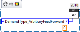
Common Feed Forward Uses/Calculations
Below are some common uses and calculations for Arbitrary Feed Forward.
Gravity Offset (Elevator)
In the case of a traditional elevator mechanism, there is a constant force due to gravity affecting the mechanism. Because the force is constant, we can determine a constant offset to keep the elevator at position when error is zero.
Use either the Phoenix Tuner Control Tab or Joystick control in your robot code to apply output to the elevator until it stays at a position without moving. Use Phoenix Tuner (plotter or Self-test Snapshot) to measure the output value - this is the Arbitrary Feed Forward value needed to offset gravity.
If we measure a motor output of 7% to keep position, then our java code for Arbitrary Feed Forward with Motion Magic would look like this:
double feedforward = 0.07;
_motorcontroller.set(ControlMode.MotionMagic, targetPos, DemandType.ArbitraryFeedForward, feedforward);
Tip
If your elevator mechanism will change weight while in use (i.e. pick up a heavy game piece), it is helpful to measure gravity offsets at each expected weight and switch between Arbitrary Feed Forward values as needed.
Gravity Offset (Arm)
In the case of an arm mechanism, the force due to gravity will change as the arm moves through its range of motion. In order to compensate for this, we will need to measure a gravity offset at the highest force (arm at horizontal position) and then scale the value with trigonometry.
To start, use either the Phoenix Tuner Control Tab or Joystick control in your robot code to apply output to the arm until it stays at the horizontal position without moving. Use Phoenix Tuner (plotter or Self-test Snapshot) to measure the output value - this is the base component of our Arbitrary Feed Forward value.
For scaling the value, the cosine term of trigonometry matches the scaling we need for our rotating arm. The cosine term is at maximum value (+1) when at horizontal (0 degrees or radians) and is at 0 when the arm is vertical (90 degrees or pi/2 radians). To use this cosine value as a scalar, we will need to determine our current angle. This requires knowing the current arm position and number of position ticks per degree, then converting to units of radians.
Note
Trigonometry uses 0 for the angle at horizontal. To account for this, we need to subtract the measured horizontal position value before we calculate our angle. This means we will have a positive angle above horizontal and a negative angle below horizontal.
Warning
The java cosine function requires units to be in radians.
int kMeasuredPosHorizontal = 840; //Position measured when arm is horizontal
double kTicksPerDegree = 4096 / 360; //Sensor is 1:1 with arm rotation
int currentPos = _motorcontroller.getSelectedSensorPosition();
double degrees = (currenPos - kMeasuredPosHorizontal) / kTicksPerDegree;
double radians = java.lang.Math.toRadians(degrees);
double cosineScalar = java.lang.Math.cos(radians);

double maxGravityFF = 0.07;
_motorcontroller.set(ControlMode.MotionMagic, targetPos, DemandType.ArbitraryFeedForward, maxGravityFF * cosineScalar);
Calculating Velocity Feed Forward gain (kF)
A typical strategy for estimating the necessary motor output is to take the target velocity and multiplying by a tuned/calculated scalar. More advanced feed forward methods (gravity compensation, custom velocity and acceleration feed forwards, static offsets, etc.) can be done with the arbitrary feed forward features from the previous section..
Note
The velocity feed forward (kF) is different from the Arbitrary Feed Forward in that it is a specialized feed forward designed to approximate the needed motor output to achieve a specified velocity.
Do I need to calculate kF?
If using any of the control modes, we recommend calculating the kF:
Velocity Closed Loop: kF is multiplied by target velocity and added to output.
Current (Draw) Closed Loop: kF is multiplied by the target current-draw and added to output.
MotionMagic/ MotionProfile / MotionProfileArc: kF is multiplied by the runtime-calculated target and added to output.
Note
When using position closed loop, it is generally desired to use a kF of ‘0’. During this mode target position is multiplied by kF and added to motor output. If providing a feedforward is necessary, we recommend using the arbitrary feed forward term (4 param Set) to better implement this.
How to calculate kF
Using Tuner (Self-test Snapshot or Plotter), we’ve measured a peak velocity of 9326 native units per 100ms at 100% output. This can also be retrieved using getSelectedSensorVelocity (routine or VI).
However, many mechanical systems and motors are not perfectly linear (though they are close). To account for this, we should calculate our feed forward using a measured velocity around the percent output we will usually run the motor.
For our mechanism, we will typically be running the motor ~75% output. We then use Tuner (Self-test Snapshot or Plotter) to measure our velocity - in this case, we measure a velocity of 7112 native units per 100ms.
Now let’s calculate a Feed-forward gain so that 75% motor output is calculated when the requested speed is 7112 native units per 100ms.
F-gain = (75% X 1023) / 7112 F-gain = 0.1079
Let’s check our math, if the target speed is 7112 native units per 100ms, Closed-loop output will be (0.1079 X 7112) => 767.38 (75% of full forward).
Note
The output of the PIDF controller in Talon/Victor uses 1023 as the “full output”.
Note
The kF feature and arbitrary feed-forward feature are not the same. Arbitrary feed-forward is a supplemental term [-1,1] the robot application can provide to add to the output via the set() routine/VI.
Motion Magic / Position / Velocity / Current Closed Loop Closed Loop
Closed-looping the position/velocity value of a sensor is explained in this section. This section also applies to the current (draw) closed loop mode.
Relevant source examples can be found at:
https://github.com/CrossTheRoadElec/Phoenix-Examples-Languages
https://github.com/CrossTheRoadElec/Phoenix-Examples-LabVIEW
The general steps are:
Selecting the sensor type (see previous Bring-Up sections)
Confirm motor and sensor health (see previous Bring-Up section on sensor)
Confirm sensor phase (see previous Bring-Up sections)
Collect max sensor velocity information (see calculating kF section)
Bring up plotting interface so you can visually see sensor position and motor output. This can be done via Tuner Plotter, or through LabVIEW/SmartDash/API plotting.
Configure gains and closed-loop centric configs.
Note
If you are using current closed-loop, than a sensor is not necessary.
Note
Current closed loop is not available on Victor SPX, it is only available on Talon SRX.
Once these previous checks are done, continue down to the gain instructions.
Note
This assumes all previous steps have been followed correctly.
Checkout the relevant example from CTREs GitHub.
Set all of your gains to zero. Use either API or Phoenix Tuner.
If not using Position-Closed loop mode, set the kF to your calculated value (see previous section).
If using Motion Magic, set your initial cruise velocity and acceleration (section below).
Deploy the application and use the joystick to adjust your target. Normally this requires holding down a button on the gamepad (to enter closed loop mode).
Plot the sensor-position to assess how well it is tracking. This can be done with WPI plotting features, or with Phoenix Tuner.
In this example the mechanism is the left-side of a robot’s drivetrain. The robot is elevated such that the wheels spin free. In the capture below we see the sensor position/velocity (blue) and the Active Trajectory position/velocity (brown/orange). At the end of the movement the closed-loop error (which is in raw units) is sitting at ~1400.units. Given the resolution of the sensor this is approximately 0.34 rotations (4096 units per rotation). Another note is that when the movement is finished, you can freely back-drive the mechanism without motor-response (because PID gains are zero).
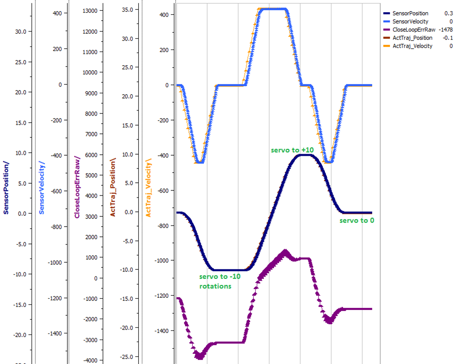
Setting Motion Magic Cruise Velocity And Acceleration
The recommended way to do this is to take your max sensor velocity (previous section).
Suppose your kMaxSensorVelocity is 9326 units per 100ms. A reasonable initial cruise velocity may be half of this velocity, which is 4663.
Config 4663 to be the cruiseVelocity via configMotionCruiseVelocity routine/VI.
Next lets set the acceleration, which is in velocity units per second (where velocity units = change in sensor per 100ms). This means that if we choose the same value of 4663 for our acceleration, than Motion Magic will ensure it takes one full second to reach peak cruise velocity.
In short set the acceleration to be the same 4663 value via configMotionAcceleration routine/VI.
Later you can increase these values based on the application requirements.
Dialing kP
Next we will add in P-gain so that the closed-loop can react to error. In the previous section, after running the mechanism with just F-gain, the servo appears to settle with an error or ~1400.
Given an error of (~1400.), suppose we want to respond with another 10% of throttle. Then our starting kP would be….
(10% X 1023) / (1400) = 0.0731 Now let’s check our math, if the Talon SRX sees an error of 1400 the P-term will be 1400 X 0.0731= 102 (which is about 10% of 1023) kP = 0.0731
Apply the P -gain programmatically using your preferred method. Now retest to see how well the closed-loop responds to varying loads.
Retest the maneuver by holding button 1 and sweeping the gamepad stick. At the end of this capture, the wheels were hand-spun to demonstrate how aggressive the position servo responds. Because the wheel still back-drives considerably before motor holds position, the P-gain still needs to be increased.
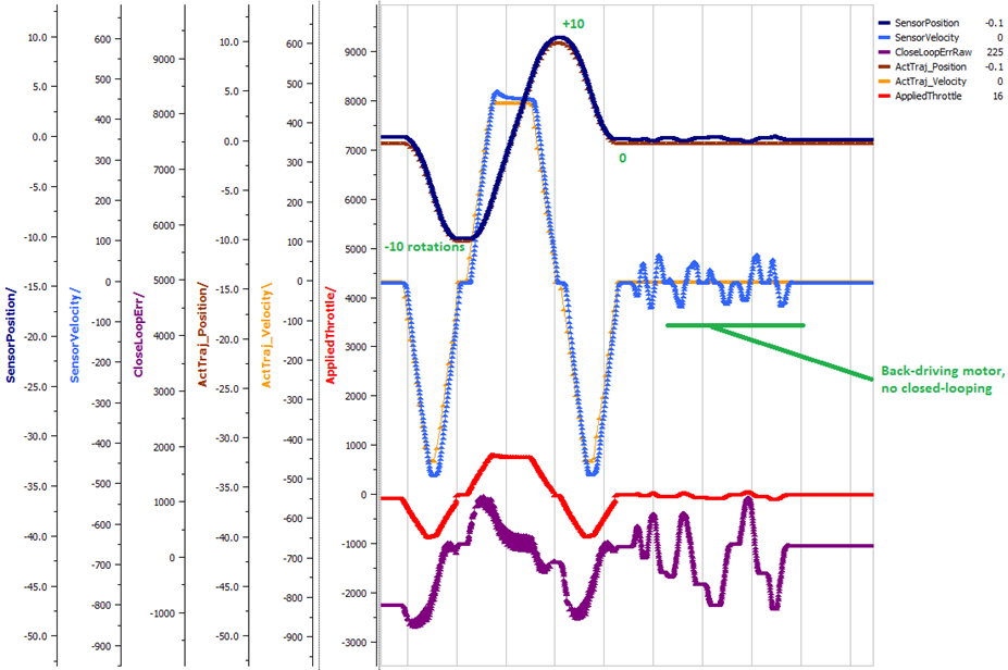
Double the P-gain until the system oscillates (by a small amount) or until the system responds adequately.
After a few rounds the P gain is at 0.6.
Scope captures below show the sensor position and target position follows visually, but back-driving the motor still shows a minimal motor response.
After several rounds, we’ve landed on a P gain value of 3. The mechanism overshoots a bit at the end of the maneuver. Additionally, back-driving the wheel is very difficult as the motor-response is immediate (good).
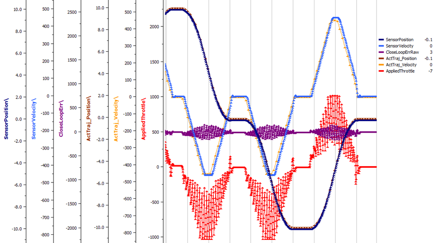
Once settles, the motor is back-driven to assess how firm the motor holds position.
The wheel is held by the motor firmly.
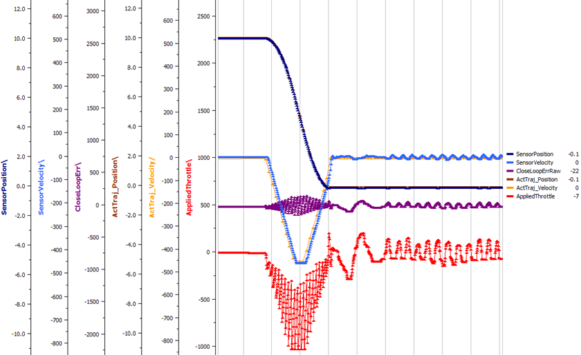
Dialing kD
To resolve the overshoot at the end of the maneuver, D-gain is added. D-gain can start typically at 10 X P-gain.
With this change the visual overshoot of the wheel is gone. The plots also reveal reduced overshoot at the end of the maneuver.
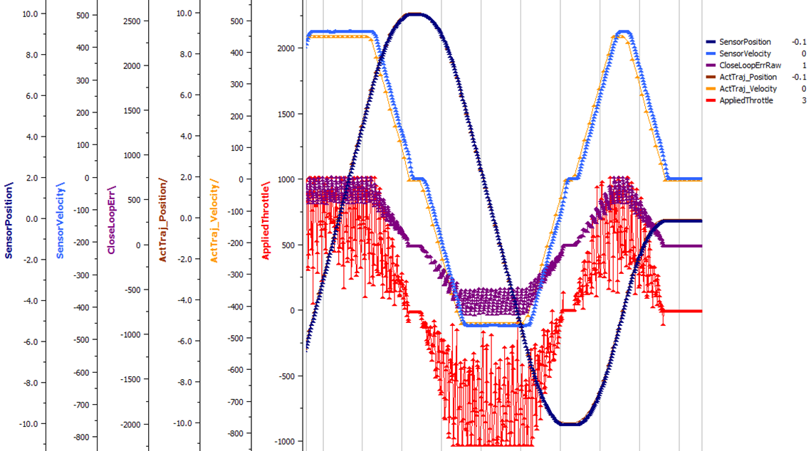
Dialing kI
Typically, the final step is to confirm the sensor settles very close to the target position. If the final closed-loop error is not quite close enough to zero, consider adding I-gain and I-zone to ensure the Closed-Loop Error ultimately lands at zero (or close enough).
In testing the closed-loop error settles around 20 units, so we’ll set the Izone to 50 units (large enough to cover the typical error), and start the I-gain at something small (0.001).
Keep doubling I-gain until the error reliably settles to zero.
With some tweaking, we find an I-gain that ensures maneuver settles with an error of 0.
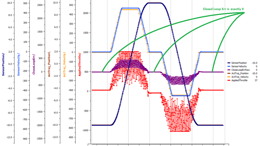
If using Motion Magic, the acceleration and cruise-velocity can be modified to hasten/dampen the maneuver as the application requires.
Auxiliary Closed Loop PID[1] Walkthrough
The auxiliary closed loop can be used to provide a differential output component to a multi motor controller system. See Auxiliary Closed Loop PID[1] for an explanation of the Auxiliary Closed Loop feature - below is a step-by-step walkthrough.
Tip
Be sure to look at the examples that are provided. Any example that has Auxiliary in the name or is named “RemoteClosedLoop” makes use of these features.
Examples can be found here: https://github.com/CrossTheRoadElec/Phoenix-Examples-Languages
We strongly encourage using the examples first, then only implementing PID[1] in your robot code once comfortable with the examples.
As an example, we will use a differential drive train with 2 encoders on each side and a pigeon.
Decide which side’s master motor controller is the ultimate master, i.e. the Talon/Victor that will calculate both the linear (PID0) and turn (PID1) component. This example will use the right side as the ultimate master side.
Configure all remaining motor controllers on the right side to follow the ultimate master motor controller.
Configure all motor controllers on the left side to auxiliary follow the master motor controller
Note
Alternatively, you can configure one motor controller on the left side to auxiliary follow the master motor controller, and the remaining to follow the auxiliary follower. Note this will introduce additional lag (typically 10ms).
Example below on how to follow the ultimate master.
_follower.follow(_ultimateMasterTalon, FollowerType.AuxOutput1); // follower will apply PID[0] - PID[1] while master applies PID[0] + PID[1], or vice versa
Configure PID[0] of the ultimate master motor controller. The example will use the sensor sum of the local encoder and of the other side’s encoder.
This requires having Sum0 Term configured to use the local encoder and Sum1 Term configured to use a RemoteFilter0.
Note
RemoteFilter 0 or 1 has to be configured to capture the other side’s encoder using either a RemoteSRX or CANifier.
See Bring Up: Differential Sensors for information on bringing up the sensors for differential setups.
Configure PID[1] of the ultimate master motor controller. The example will use RemoteSensor1 configured to capture the Pigeon’s Yaw value.
See Bring Up: Differential Sensors for information on bringing up the sensors for differential setups, and Bring Up: Remote Sensors for bringing up Pigeon IMU as a remote sensor.
Determine if the master controller should use the output of PID[0] + PID[1] or if it should use PID[0] - PID[1]. This will depend on the polarity of the sensors, which side of the drivetrain is the ultimate master, and the desired corrective motion.
The auxiliary follower will use whichever sign the master does not use in order to control the differential.
When closed-looping the drive train, utilize the 4 parameter set method, specifying a setpoint for the sum of the encoders and a setpoint for the Pigeon IMU yaw.
_rightMaster.set(ControlMode.Position, forward, DemandType.AuxPID, _targetAngle); // _targetAngle is in Pigeon units, 8192 units per 360'LabVIEW snippet below that uses 4 param set.
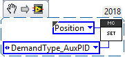
Tune the PID for both the primary and auxiliary PID using the above methods.
Tip
Primary and Auxiliary PID can initially be tuned independently to simplify the tuning process. Tune the primary PID gains while keeping the Auxiliary target constant, then tune the auxiliary PID gains while keeping the primary target constant (ie. using zero-turn movement). The primary and auxiliary gain sets can then be further tuned when executing motion using both PID loops simultaneously.
Motion Profiling Closed Loop
The above guide shows how to dial PID gains for all closed looping, this guide will talk about how to utilize Motion Profiling using a BufferedStream object.
Note
It is strongly recommended to use the MotionProfiling example first to become familiar with Motion Profiling, and only after having used the example should you try to implement it in your own robot code
Tip
The Buffered stream object is a new object introduced in 2019 designed to make motion profiling easier than ever. The legacy API and the examples that use it are still available.
Create a motion profile
Using Excel or a path generating program, you need to create a series of points that specify the target position, velocity, and the time to the next point. If you are using an example, there is an excel sheet inside the example folder that does this for you named Motion Profile Generator. Use this to get started on creating motion profiles.
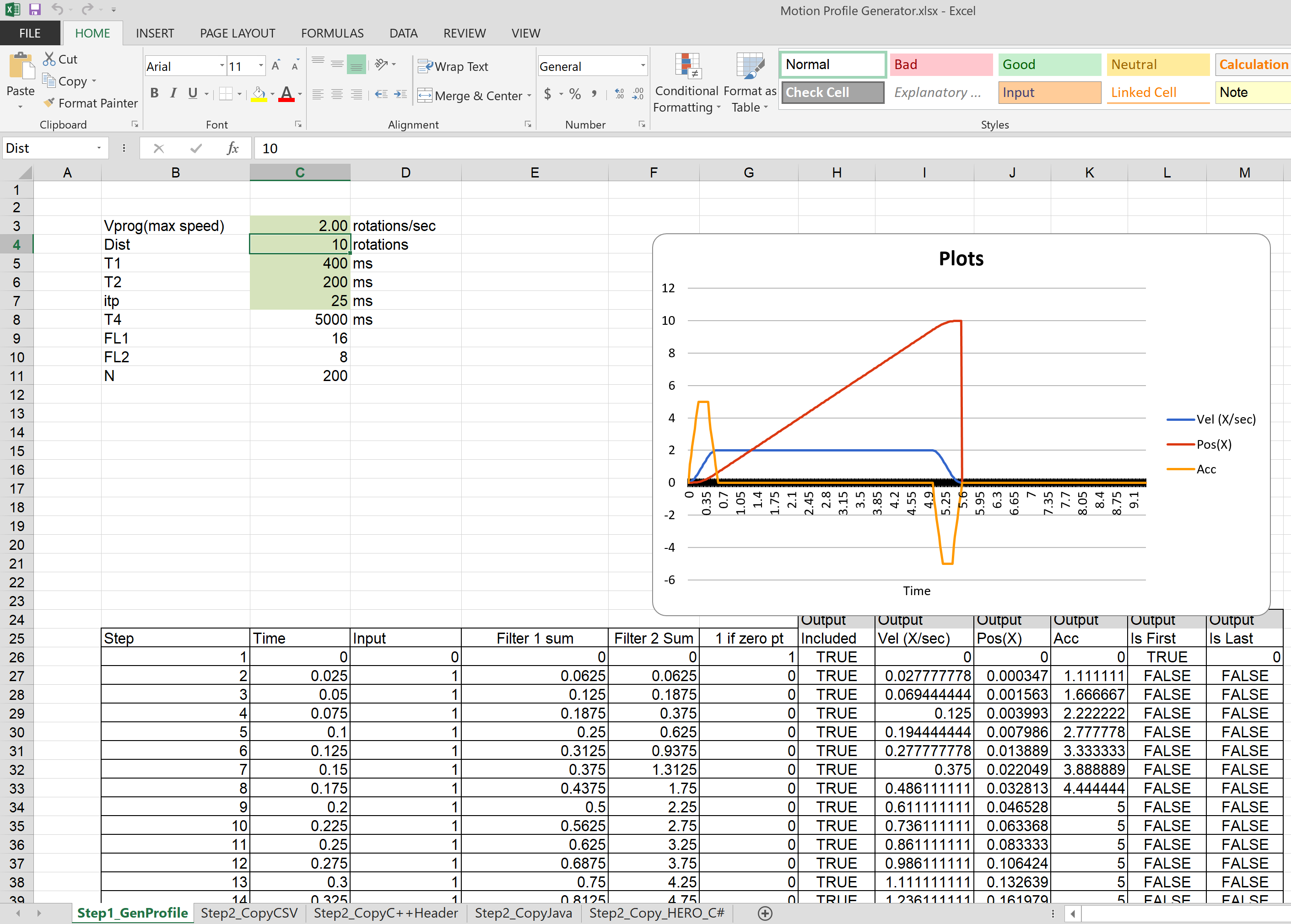
Upload it to the robot
This can be done either by copy-pasting all the points into the robot application as an array or by copy-pasting the file onto the Robot Controller and using a File operation to read it. The Java/C++ examples show copy-pasting the points into an array, and the excel document we provide has a page that automatically generates the array for you to copy paste.
public static double [][]Points = new double[][]{
        {0,     0       ,25},
        {0.000347222222222222,  1.666666667     ,25},
        {0.0015625,     4.166666667     ,25},
        {0.00399305555555556,   7.5     ,25},
        .
        .
        .
        {9.99756944444445,      5       ,25},
        {9.99913194444445,      2.5     ,25},
        {9.99982638888889,      0.833333333     ,25},
        {10,    0       ,25}
};
LabVIEW, on the other hand, uses the file operations to read a csv file and feed the points read from it into an array.
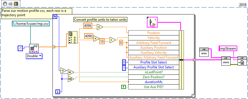
Tip
Drag and drop the image above into your Begin.vi block diagram
Note
The above image also has the next step, Write the points to a Buffered Stream included in it
Write the points to a Buffered Stream
Now you need to write all the points onto a buffered stream object. This is done by calling the Write method and passing a trajectory point that has the specified position and velocity into the object. Be sure that the first point has zeroPos set to true if you wish to zero the position at the start of the profile and that the last point has isLast set to true so the profile recognizes when it’s done.
Java example:
/* Insert every point into buffer, no limit on size */
for (int i = 0; i < totalCnt; ++i) {

        double direction = forward ? +1 : -1;
        double positionRot = profile[i][0];
        double velocityRPM = profile[i][1];
        int durationMilliseconds = (int) profile[i][2];

        /* for each point, fill our structure and pass it to API */
        point.timeDur = durationMilliseconds;
        point.position = direction * positionRot * Constants.kSensorUnitsPerRotation;           // Convert Revolutions to Units
        point.velocity = direction * velocityRPM * Constants.kSensorUnitsPerRotation / 600.0;   // Convert RPM to Units/100ms
        point.auxiliaryPos = 0;
        point.auxiliaryVel = 0;
        point.profileSlotSelect0 = Constants.kPrimaryPIDSlot; /* which set of gains would you like to use [0,3]? */
        point.profileSlotSelect1 = 0; /* auxiliary PID [0,1], leave zero */
        point.zeroPos = (i == 0); /* set this to true on the first point */
        point.isLastPoint = ((i + 1) == totalCnt); /* set this to true on the last point */
        point.arbFeedFwd = 0; /* you can add a constant offset to add to PID[0] output here */

        _bufferedStream.Write(point);
}
Call startMotionProfile
With the Buffered Stream object fully written to, call startMotionProfile and the motor controller will begin executing once the specified number of points have been buffered into it. Do not call Set after this, the motor controller will execute on its own.
Note
Ensure MotorSafety is Disabled. Using the new API with MotorSafety enabled causes undefined behavior. If you wish to use MotorSafety with motion profiling, use the Legacy API.
Check isMotionProfileFinished
After having started the motion profile, you should check when the profile is done by polling IsMotionProfileFinished until it returns true. Once it is true, you know the profile has reached its last point and is complete, so you can move on to the next action.
if (_master.isMotionProfileFinished()) {
        Instrum.printLine("MP finished");
}
Motion Profiling Arc Closed Loop
In addition to the motion profile mode, there is a similar control mode that integrates auxiliary closed loop features. This is called Motion Profile Arc control mode, and utilizes everything that’s been covered in the previous sections.
Below is a guide on how to get Motion Profiling Arc up and running, using the new Buffered Stream API.
Note
This is also an example that is available on our examples repo
Note
The steps for using motion profile arc are very similar and reference the steps for creating a normal motion profile. Read them first
- Steps for using Motion Profile Arc:
Configure all the motor controllers to use the correct sensors
This involves bringing up all the sensors on their respective CAN devices
This also requires setting up remote sensors and auxiliary closed loops, as detailed in the sections above
Create a motion profile. This is the most unique step from a normal motion profile because it will integrate the auxiliary position variable in some way with the profile. If you wish to just make sure the robot is driving straight, generate a normal profile and zero the auxiliary position.
Upload the points to the robot. This is done the same way as for a normal motion profile
Write the points to a Buffered Stream object. This is also done the same way, but be sure to include the auxiliary position and auxiliary velocity points as well as setting useAuxPID to true
Call startMotionProfile. Everything regarding normal motion profile is the same as motion profile arc, except that you also need to pass ControlMode.MotionProfileArc as the motion profile control mode
Wait until isMotionProfileFinished returns true. This is the same as a normal motion profile.
Mechanism is Finished Command
Often it is necessary to move a mechanism to a setpoint and ensure that it has properly reached its final position before moving on to the next command. A proper implementation requires the following:
waiting long enough to ensure CAN framing has provided fresh data. See setStatusFramePeriod() to modify update rates.
waiting long enough to ensure mechanism has physically settled. Otherwise closed-loop overshoot (due to inertia) will not be corrected.
Warning
If using Motion Magic control mode, robot code should additionally poll getActiveTrajectoryPosition() routine/VI to determine when final target position has been reached. This is because the closed-loop error corresponds how well the position profile is tracking, not when profiled maneuver is complete.
The general requirements are to periodically monitor the closed-loop error provided the following:
The latest closed-loop error (via API).
The threshold that the closed-loop error must be within to be considered acceptable.
How long the closed-loop error has been acceptable.
The threshold of how long the error must be acceptable before moving on to the next command.
An example of this is shown below in Java, within a class that implements the Command interface
int kErrThreshold = 10; // how many sensor units until its close-enough
int kLoopsToSettle = 10; // how many loops sensor must be close-enough
int _withinThresholdLoops = 0;

// Called repeatedly when this Command is scheduled to run
@Override
protected void execute() {
    /* Check if closed loop error is within the threshld */
    if (talon.getClosedLoopError() < +kErrThreshold &&
        talon.getClosedLoopError() > -kErrThreshold) {

        ++_withinThresholdLoops;
    } else {
        _withinThresholdLoops = 0;
    }
}

// Make this return true when this Command no longer needs to run execute()
@Override
protected boolean isFinished() {
    return (_withinThresholdLoops > kLoopsToSettle);
}
Warning
If using Motion Magic control mode, robot code should additionally poll getActiveTrajectoryPosition() routine/VI to determine when final target position has been reached. This is because the closed-loop error corresponds how well the position profile is tracking, not when profiled maneuver is complete.
Closed-Loop Configurations
The remaining closed-loop centric configs are listed below.
General Closed-Loop Configs
Name |
Description |
PID 0 Primary Feedback Sensor |
Selects the sensor source for PID0 closed loop, soft limits, and
value reporting for the SelectedSensor API.
|
PID 0 Primary Sensor Coefficient |
Scalar (0,1] to multiply selected sensor value before using.
Note this will reduce resolution of the closed-loop.
|
PID 1 Aux Feedback Sensor |
Select the sensor to use for Aux PID[1]. |
PID 1 Aux Sensor Coefficient |
Scalar (0,1] to multiply selected sensor value before using.
Note that this will reduce the resolution of the closed-loop.
|
PID 1 Polarity |
False: motor output = PID[0] + PID[1], follower = PID[0] - PID[1].
True : motor output = PID[0] - PID[1], follower = PID[0] + PID[1].
This only occurs if follower is an auxiliary type.
|
Closed Loop Ramp |
How much ramping to apply in seconds from neutral-to-full.
A value of 0.100 means 100ms from neutral to full output.
Set to 0 to disable.
Max value is 10 seconds.
|
Closed-Loop configs per slot (four slots available)
Name |
Description |
|---|---|
kF |
Feed Fwd gain for Closed loop. See documentation for calculation details. If using velocity, motion magic, or motion profile, use (1023 * duty-cycle / sensor-velocity-sensor-units-per-100ms) |
kP |
Proportional gain for closed loop. This is multiplied by closed loop error in sensor units. Note the closed loop output interprets a final value of 1023 as full output. So use a gain of ‘0.25’ to get full output if err is 4096u (Mag Encoder 1 rotation) |
kI |
Integral gain for closed loop. This is multiplied by closed loop error in sensor units every PID Loop. Note the closed loop output interprets a final value of 1023 as full output. So use a gain of ‘0.00025’ to get full output if err is 4096u (Mag Encoder 1 rotation) after 1000 loops |
kD |
Derivative gain for closed loop. This is multiplied by derivative error (sensor units per PID loop). Note the closed loop output interprets a final value of 1023 as full output. So use a gain of ‘250’ to get full output if derr is 4096u per (Mag Encoder 1 rotation) per 1000 loops (typ 1 sec) |
Loop Period Ms |
Number of milliseconds per PID loop. Typically, this is 1ms. |
Allowable Error |
If the closed loop error is within this threshold, the motor output will be neutral. Set to 0 to disable. Value is in sensor units. |
I Zone |
Integral Zone can be used to auto clear the integral accumulator if the sensor pos is too far from the target. This prevent unstable oscillation if the kI is too large. Value is in sensor units. |
Max Integral Accum |
Cap on the integral accumulator in sensor units. Note accumulator is multiplied by kI AFTER this cap takes effect. |
Peak Output |
Absolute max motor output during closed-loop control modes only. A value of ‘1’ represents full output in both directions. |
Motion Magic Closed-Loop Configs
Name |
Description |
|---|---|
Acceleration |
Motion Magic target acceleration in (sensor units per 100ms) per second. |
Cruise Velocity |
Motion Magic maximum target velocity in sensor units per 100ms. |
S-Curve Strength |
Zero to use trapezoidal motion during motion magic. [1,8] for S-Curve, higher value for greater smoothing. |
Motion Profile Configs
Name |
Description |
Base Trajectory Period |
Base value (ms) ADDED to every buffered trajectory point.
Note that each trajectory point has an individual duration (0-127ms).
This can be used to uniformly delay every point.
|
Trajectory Interpolation Enable |
Set to true so Motion Profile Executor to linearize the target
position and velocity every 1ms. Set to false to match 2018 season
behavior (no linearization). This feature allows sending less
points over time and still having resolute control
Default is set to true.
|
Faults
“Faults” are status indicators on CTRE CAN Devices that indicate a certain behavior or event has occurred. Faults do not directly affect the behavior of a device, rather they indicate the device’s current status and highlight potential issues.
Faults are stored in two fashions. There are “live” faults that are reported in real-time, and “sticky” faults which assert persistently and stay asserted until they are manually cleared (like trouble codes in a vehicle).
Note
Sticky Faults can be cleared in Tuner and via API.
Note
Faults and Sticky Faults can be polled using Tuner-Self-test Snapshot or via API.
Tip
Motor Controllers have a sticky fault to detect if device reset during robot-enable. This is useful for detecting breaker events.

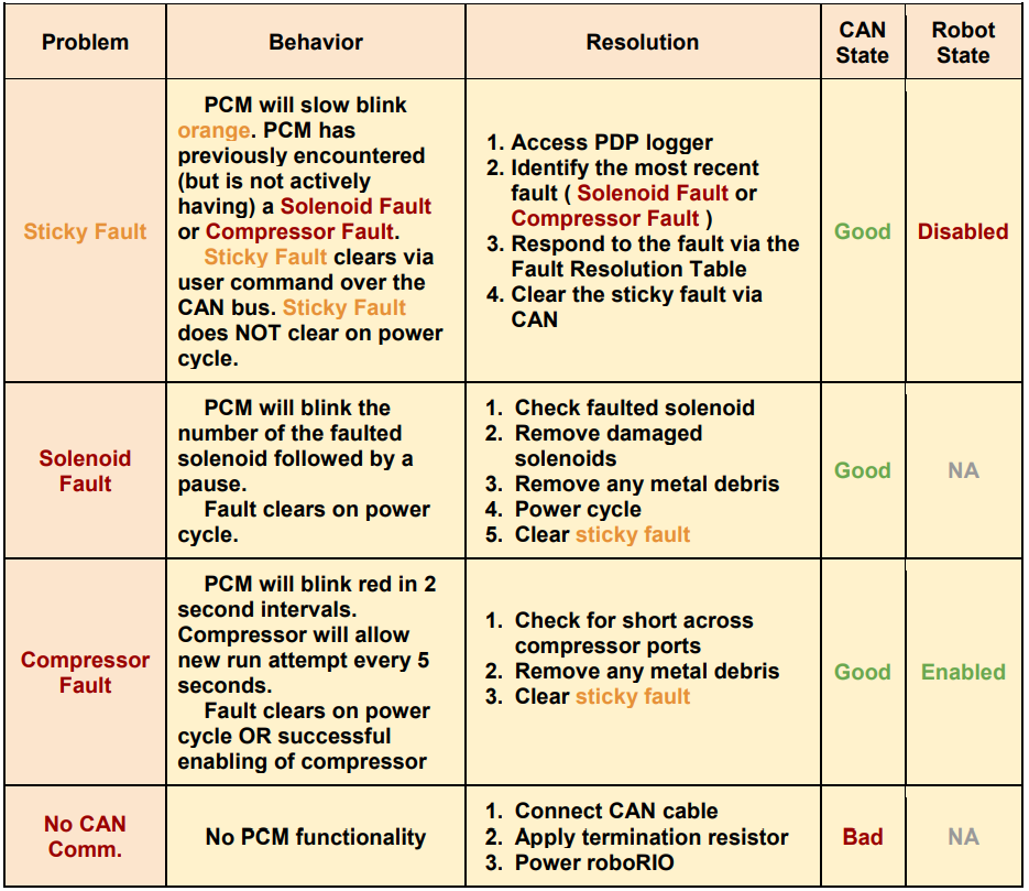
Common Device API
Setting Status Frame Periods
All Phoenix devices have a setStatusFramePeriod() routine/VI that allows for tweaking the frame periods of each status group. The status group contents and default updates rates are listed below.
Status Groups
Motor Controllers
Status 1 (Default Period 10ms):
Applied Motor Output
Fault Information
Limit Switch Information
Tip
Motor controllers that are followers can have slower update rates for this group without impacting performance.
Status 2 (Default Period 20ms):
Selected Sensor Position (PID 0)
Selected Sensor Velocity (PID 0)
Brushed Supply Current Measurement
Sticky Fault Information
Tip
Motor controllers that are followers can have slower update rates for this group without impacting performance.
Status 3 (Default Period >100ms):
Quadrature Information
Status 4 (Default Period >100ms):
Analog Input
Supply Battery Voltage
Controller Temperature
Status 8 (Default Period >100ms):
Pulse Width Information
Status 10 (Default Period >100ms):
Motion Profiling/Motion Magic Information
Status 12 (Default Period >100ms):
Selected Sensor Position (Aux PID 1)
Selected Sensor Velocity (Aux PID 1)
Status 13 (Default Period >100ms):
PID0 (Primary PID) Information
Status 14 (Default Period >100ms):
PID1 (Auxiliary PID) Information
Status 21 (Default Period >100ms):
Integrated Sensor Position (Talon FX)
Integrated Sensor Velocity (Talon FX)
Status Brushless Current (Default Period 50ms):
Brushless Supply Current Measurement
Brushless Stator Current Measurement
Pigeon IMU
General Status 1 (Default Period >100ms):
Calibration Status
IMU Temperature
Conditioned Status 9 (Default Period 10ms):
Six degree fused Yaw, Pitch, Roll
Conditioned Status 6 (Default Period 10ms):
Nine degree fused Yaw, Pitch, Roll (requires magnetometer calibration).
Conditioned Status 11 (Default Period 20ms):
Accumulated Gyro Angles
Conditioned Status 3 (Default Period >100ms):
Accelerometer derived angles
Conditioned Status 10 (Default Period >100ms):
Six degree fused Quaternion
Raw Magnetometer Status 4 (Default Period 20ms):
Unprocessed magnetometer values (x,y,z)
Biased Status 2 Gyro (Default Period >100ms):
Biased gyro values (x,y,z)
Biased Status 6 Accelerometer (Default Period >100ms):
Biased accelerometer values (x,y,z)
CANifier
General Status 1 (Default Period >100ms):
Applied LED Duty Cycles
Conditioned Status 2 (Default Period 10ms):
Quadrature Information
General Inputs
Conditioned Status 3 (Default Period >100ms):
PWM input 0 Information
Conditioned Status 4 (Default Period >100ms):
PWM input 1 Information
Conditioned Status 5 (Default Period >100ms):
PWM input 2 Information
Conditioned Status 6 (Default Period >100ms):
PWM input 3 Information
CAN bus Utilization/Error metrics
The driver station provides various CAN bus metrics under the lightning bolt tab.
Utilization is the percent of bus time that is in use relative to the total bandwidth available of the 1Mbps Dual Wire CAN bus. So at 100% there is no idle bus time (no time between frames on the CAN bus).
Demonstrated here is 70% bus use when controlling 16 Talon SRXs, along with 1 Pneumatics Control Module (PCM) and the Power Distribution Panel (PDP).
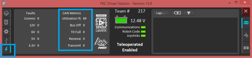
The “Bus Off” counter increments every time the CAN Controller in the roboRIO enters “bus-off”, a state where the controller “backs off” transmitting until the CAN bus is deemed “healthy” again.
A good method for watching it increment is to short/release the CAN bus High and Low lines together to watch it enter and leave “Bus Off” (counter increments per short). The “TX Full” counter tracks how often the buffer holding outgoing CAN frames (RIO to CAN device) drops a transmit request. This is another common symptom when the roboRIO no longer is connected to the CAN bus.
The “Receive” and “Transmit” signal is shorthand for “Receive Error Counter” and “Transmit Error Counter”.
These signals are straight from the CAN bus, and track the error instances occurred “on the wire” during reception and transmission respectively. These counts should always be zero. Attempt to short the CAN bus and you can confirm that the error counts rise sharply, then decrement back down to zero when the bus is restored (remove short, reconnect daisy chain).
When starting out with the FRC control system and Talon SRXs, it is recommended to watch how these CAN metrics change when CAN bus is disconnected from the roboRIO and other CAN devices to learn what to expect when there is a harness or a termination resistor issue. Determining hardware related vs software related issues is key to being successful when using many CAN devices.
Followers
Motor controllers that are followers can set Status 1 and Status 2 to 255ms(max) using setStatusFramePeriod.
The Follower relies on the master status frame allowing its status frame to be slowed without affecting performance.
This is a useful optimization to manage CAN bus utilization.
Detecting device resets
All Phoenix devices have a hasResetOccurred()/VI routine that will return true if device reset has been detected since previous call.
Detecting this is useful for two reasons:
Reapply any custom status frame periods that were set using setStatusFramePeriod().
Telemetry / general troubleshooting (in addition to sticky fault, see tip below).
Tip
Motor Controllers have a sticky fault to detect if device reset during robot-enable. This is useful for detecting breaker events.
Support
GitHub Examples
All documentation and examples can be found in the public organization… https://github.com/CrossTheRoadElec
There many examples in all three FRC languages available at… https://github.com/CrossTheRoadElec/Phoenix-Examples-Languages https://github.com/CrossTheRoadElec/Phoenix-Examples-LabVIEW
Contact information
CTR Staff can be reached out with the contact information available at…
https://store.ctr-electronics.com/contact-us/
The best method for contacting support is via our email (support@ctr-electronics.com). This allows for simple sharing of screenshots and supplemental file attachments.
If seeking help troubleshooting hardware issues, please answer the questions under “Warranty” inside the “Support Request form”.
To resolve your issue in an expedient fashion, we need the following:
What behavior are you seeing versus what are you expecting to observe?
What procedure are you following to reproduce the issue?
If using the roboRIO, we need a screenshot of the Phoenix Tuner to confirm firmware version, gain values, etc.
If using the roboRIO, we need a screenshot of a Self-test Snapshot taken during the undesired behavior.
Part numbers of all devices involved. For example, if using a sensor, what is the sensor part number?
Firmware versions of all devices involved.
If using motor controllers, are they on CAN bus or PWM?
If using Phoenix, screenshot of the About form in Phoenix Tuner / Phoenix LifeBoat.
Troubleshooting and Frequently Asked Questions
Driver Station Messages
What do I do when I see errors in Driver Station?
DS Errors should be addressed as soon as they appear. This is because:
Phoenix API will report if a device is missing, not functioning, has too-old firmware, etc.
If errors are numerous and typical, then users cannot determine if there is a new problem to address.
A large stream of errors can bog down the DriverStation/roboRIO. Phoenix Framework has a debouncing strategy to ensure this does not happen, but not all libraries do this.
Phoenix DS errors occur on call. Meaning VIs/API functions must be called in robot code for any errors to occur. When an error does occur, a stack trace will report where in the robot code to look.
The Debouncing Strategy that Phoenix uses is 3 seconds long. Phoenix keys a new error on device ID & function. This is to ensure that all unique errors are logged while making sure the DriverStation/roboRIO does not generate excessive errors.
Driver Station says the firmware is too old.

Use Phoenix Tuner to update the firmware of the device.
Note that the robot application must be restarted for the firmware version check to clear. This can be done by redeploying the robot application or simply restarting the robot.
Driver Station says the firmware could not be retrieved and to check the firmware and ID.
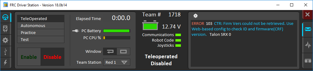
This usually indicates that your device ID is wrong in your robot software, or your firmware is very old.
Use Phoenix Tuner to check your device IDs and make sure your firmware is up-to-date.
Driver Station Says “ERROR 7 Call Library Function Node…”
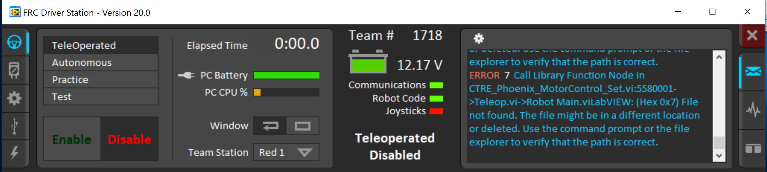
This can be seen when the Phoenix libraries are not present on the roboRIO.
This can be fixed by following the process to prepare the roboRIO for LabVIEW.
Driver Station Says Variant To Data in …
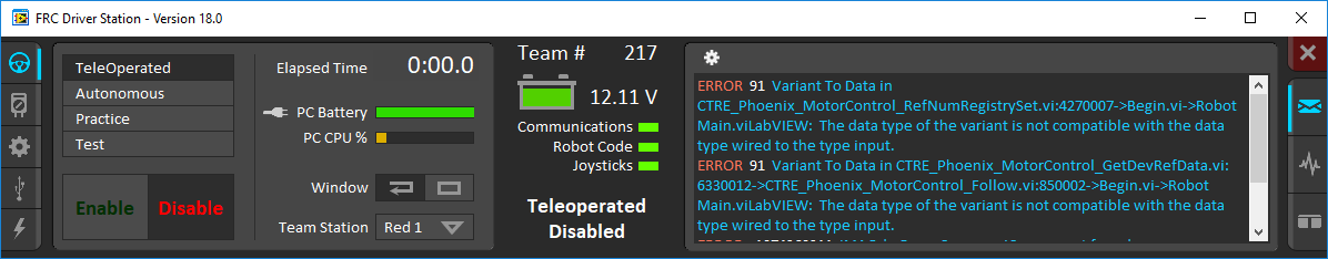
This is usually caused by a diagram disable structure around a MotorController or EnhancedMotorController VI
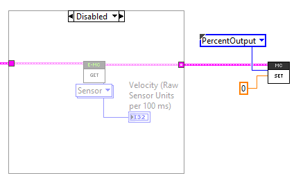
In order to fix this, you must wire the device reference through the enabled state of the diagram disabled block


PCM
My compressor turns on and I have air pressure, but why isn’t my solenoid turning on?
Check the red LED for the Solenoid channel. If the LED turns on as expected, make sure the Solenoid Voltage Jumper is set to the proper voltage (12 or 24 volts).
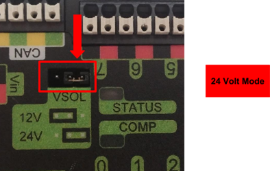
Warning
If you attempt to drive 12V Solenoids with 24V, you will damage the solenoids. If you attempt to drive 24V Solenoids with 12V, you may damage the solenoids.
Why isn’t the Compressor turning on? Why does the PCM COMP LED not turn on?
In order for the compressor output to activate, certain conditions have to be met.
The robot must be enabled.
Robot software must have a pneumatics related object (compressor or solenoid).
PCM must be powered/wired to CAN bus.
PCM’s device ID must match robot software.
If any of these conditions are not met, the compressor will not activate. The best method for root-causing wiring or software issues is to check the following conditions and symptoms in sequential order.
PCM must be powered.
This can be checked by ensuring the STATUS LED is illuminated. If the STATUS LED is off, recheck the power path from the PDP to the PCM. If using the fused output of the PDP, check the fuse. This can be done by removing the fuse and checking its continuity/DC-resistance, or simply by measuring the voltage across the power/ground wires that connect into the PCM’s Vin Weidmuller input (should be approximately battery voltage or ~12V).
PCM must be on CAN Bus
The PCM must be connected to the CAN bus chain. If a PCM does not see a healthy CAN bus it will blink the STATUS LED red (See User’s Guide for LED States).
Additionally the PCM will not appear in Phoenix Tuner or will report loss of communication. This is important to check because a red STATUS LED pattern may also reflect a fault condition (if robot is enabled). To distinguish a fault condition, confirm the PCM does appear in the configuration page, and use the Self-test Snapshot to identify which fault condition is occurring.
If these negative symptoms are noticed, recheck CAN bus harness and termination resistors. If several CAN devices are also blinking red then check the CANH/CANL chain. If it’s just the PCM then inspect the Weidmuller CAN contacts on the PCM.
If the PCM CAN connection is healthy, then it should slowly blink green (when robot is disabled). It may blink orange instead to signal that a sticky fault has been logged. Use the Self-test Snapshot in Phoenix Tuner to inspect and clear sticky faults.
More information on faults and sticky faults is available under PCM Faults.
Confirm PCM is not faulting.
At this point the PCM should appear in the Phoenix Tuner CAN Devices tab. Using the Self-test Snapshot, determine if any faults are occurring “Now”. Checking the sticky faults can also be helpful for identifying recent faults.
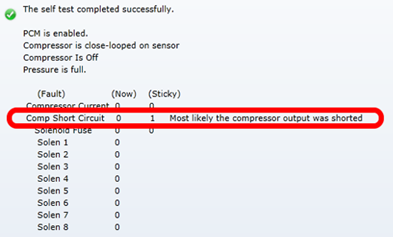
More information on faults and sticky faults is available under PCM Faults.
The Robot must be enabled, Robot Software must create a pneumatics related object.
The PCM should appear in the Phoenix Tuner CAN Devices tab, however when enabling the robot, the STATUS LED may not transition to strobe green. Additionally, when performing the Self-test Snapshot, the report may read “PCM IS NOT ENABLED”
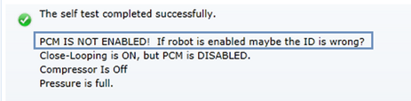
This is typical if the robot is not enabled OR if the robot application did not create any Solenoid or Compressor objects. This is how the programming API signals the intent of using pneumatics, and thus enabling the PCM.
Make sure the robot is truly enabled by looking at the Driver Station.
Instructions for creating a Solenoid, DoubleSolenoid or Compressor object in LabVIEW, C++, and Java can be found at https://docs.wpilib.org, (search for keyword “PCM”). Creating a single object of any pneumatics related type is sufficient for enabling the PCM (and therefore enabling compressor closed-loop).
Note
In order to create a software object for Solenoid or Compressor, typically the caller may specify the CAN Device ID (not specifying it typically defaults to selecting Device ID zero). This value must match what is specified in Phoenix Tuner. For more information see Set Device IDs.
Tip
Since PCMs default with a device ID of zero, users only using one PCM may prefer to leave the default device ID. PCM Device ID range is allowed to overlap with the device ID of other non-PCM CAN devices.
Pressure Switch must be wired and must signal “not full”.
Even though a robot and PCM are enabled, the compressor output will not activate if the pressure switch is not connected or is indicating full pressure. The only way to inspect this reliably is to perform the Self-test Snapshot in Phoenix Tuner.
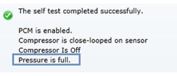
If Self-test Snapshot is reading “pressure is full” when the pressure gauge clearly is not full, recheck the wiring on the pressure switch and PCM.
The COMP LED must illuminate green.
If the COMP LED is off then the PCM is not activating the compressor output. The Self-test Snapshot is the best method for determining why. If the PCM is not present in the Phoenix Tuner recheck section the first 2 steps of this process. If the PCM is present and not enabled, recheck the robot program. If the Compressor is not “close-looped on sensor”, then the robot application must be using programming API to disable it. If pressure is erroneously reading “full”, recheck the previous step.
Compressor must be wired and functional.
If the COMP LED is illuminated green but the compressor still is not activating, then there may be a wiring issue between the PCM and the compressor. A voltmeter can be used to confirm that the PCM is applying 12V across the high and low side compressor output, and that 12V is reaching the compressor.
Errata
Talon FX Remote Filter Device ID Must be 15 or Less
When configuring Talon FX to have a remote sensor, the filter’s device ID must be 15 or less.
Attempting to set a Remote Filter Device ID >15 in Phoenix Tuner will result in a “DI_Mismatch” error.
When running a robot program, the filter device ID will not be the expected value and so will generate an error that the remote sensor is missing on the bus. The associated fault will also be asserted and can be viewed in self-test snapshot of the Talon FX.
The actual filter device ID set will be truncated to the original set value modulo 15.
Tip
This is fixed in firmware version 21.0.1.0
Java Simulation: WPI_TalonSRX/WPI_VictorSPX Null Pointer Exception
When running simulation, the following error can occur:
Error at com.ctre.phoenix.motorcontrol.can.WPI_TalonSRX$OnPeriodicCallback.run(WPI_TalonSRX.java:208): Unhandled exception: java.lang.NullPointerException
        at com.ctre.phoenix.motorcontrol.can.WPI_TalonSRX$OnPeriodicCallback.run(WPI_TalonSRX.java:208)
        at edu.wpi.first.hal.HAL.simPeriodicBefore(HAL.java:41)
        at edu.wpi.first.wpilibj.IterativeRobotBase.loopFunc(IterativeRobotBase.java:281)
        at edu.wpi.first.wpilibj.TimedRobot.startCompetition(TimedRobot.java:117)
        at edu.wpi.first.wpilibj.RobotBase.runRobot(RobotBase.java:335)
        at edu.wpi.first.wpilibj.RobotBase.lambda$startRobot$0(RobotBase.java:387)
        at java.base/java.lang.Thread.run(Thread.java:834)
This occurs when multiple WPI_TalonSRX objects have been created with the same device ID or multiple WPI_VictorSPX objects have been created with the same device ID. Find and remove the extra objects from your java code.
HERO firmware compatibility with firmware 4.X
The HERO robot controller still requires v11.X firmware in the motor controllers to function correctly. This will addressed in a future release (which updates HERO).
THe HERO robot controller also still requires v0.41 firmware for Pigeon IMU. This will addressed in a future release (which updates HERO).
No S-Curve VI in LabVIEW
Pass ‘412’ as the parameter, and the desired S-Curve strength [0,8] as the value.
A value of 0 represents no S-Curving (trapezoidal profiling).
To set the S-Curve strength in LabVIEW, the following LV snippet can be used.
Tip
Drag and drop the bottom image into your LabVIEW Block Diagram.
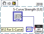
Stator Current Limit Threshold Configs
The trigger threshold current and time are not honored in 20.0.0 firmware. Stator current limit will trigger when the measured current exceeds the limit (within 1ms).
CANCoder not a remote sensor source
CANCoder is not available as a remote sensor source for Talon FX/SRX and Victor SPX. This will be addressed in a future update.
Tip
This was added in Phoenix v5.17.6. Motor Controller must be updated to 20.1 or newer.
Remote Sensors Not Working with Talon FX
The remote sensor feature does not work with Talon FX.
Tip
This is fixed in firmware version 20.1
Kickoff Temporary Diagnostic Server may not work
The kickoff version of Tuner and temporary diagnostic server has a known issue where CAN bus devices may not show up. This has been fixed in version 1.6.0.0 of Tuner. This can be quickly checked by looking at the robot controller install tab of Tuner. If there is no purple “Restart LabVIEW Robot Code” button, Tuner is not up to date and may have this issue. Your version of Tuner should look like the following:
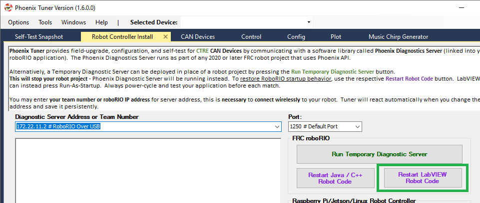
LabVIEW 2020 Deploys failing
During our system level validation, we observed a circumstance where LabVIEW permanent deploys would fail (“Connection disconnected by peer”). We are currently investigating this, but we will tentatively report the following suggestions until we complete our assessment.
When deploying LabVIEW, we recommend disconnecting Phoenix Tuner to ensure it doesn’t influence LabVIEW’s deploy process.
If deploys are consistently failing, the running LabVIEW application can be cleared via SSH with
/usr/local/frc/bin/frcKillRobot.sh -t -ror press the UnDeploy LabVIEW/Diag Server button in Tuner - Robot Controller Install. This should bring the roboRIO into an empty state whereby deploy can be re-attempted.Alternatively roboRIO could also be reset using DriverStation “Reboot roboRIO” button. This is effective if roboRIO is running a temporary deployed LV application or temporary diagnostic server.
Tip
This has been resolved in Phoenix v5.17.4.
TalonFX Current Reporting Status Frame Not Available
The Status Frame that TalonFX uses when reporting its supply and stator current is not available under the StatusFrame or StatusFrameEnhanced enum. The enum will be modified to include this frame in a future update. Currently, the following can be done to modify the Current Measurement Status Frame period:
_fx.setStatusFramePeriod(0x1240, periodMs); //0x1240 is used to identify the Current Status Frame
Tip
This has been resolved in Phoenix v5.17.6.
Talon FX Thermal Limits Low when using PWM Out-of-the-Box
Talon FX’s ship firmware has lower thermal limits that current firmware. If using the Talon FX with PWM control, users may still want to update firmware over CAN to take advantage of the higher thermal limits.
Talon FX does not support Sensor Coefficient
Configuring a sensor coefficient on Talon FX does not do anything.
Tip
This has been resolved in firmware version 20.2.3.0
Talon FX Continuous-Deadbands all the time
Talon FX will always follow a continuous deadband regardless of the mode it’s in. This results in double-deadbanding for a follower, which is seen by the applied output of the follower being slightly different than the master. Read more about Continuous Deadbanding inside Bring Up: Talon FX/SRX and Victor SPX.
Tip
This has been resolved in firmware version 20.1.0.0
Software Release Notes
This section covers the basic firmware versions that are in use.
For a complete and comprehensive list, see the full Release Notes.
Talon FX (Falcon 500) / Talon SRX / Victor SPX
The kickoff firmware is 20.0.0.0, and the latest firmware is:
Talon FX: 20.3.0.2
Talon SRX: 20.2
Victor SPX: 20.1
These versions are adequate for FRC and nonFRC use (notwithstanding known errata with HERO C#).
Talon FX 20.3 firmware update
Prevents hardware damage if Talon FX is unpowered and sufficiently back-driven.
The exact conditions are explained in this blog post.
The 20.2 firmware update
Talon FX 20.2.3.0 fixed Sensor Coefficient.
Talon FX 20.2.3.0 also supports Music.
Talon SRX 20.2 fixed an issue where the quadrature velocity measurement under certain conditions could be noisy.
The 20.1 firmware update
Remote CANCoder support was added in 20.1 for all motor controllers. Talon FX 20.1.0.0 also fixed an issue where Talon FX follower is negligibly different than master.
CANCoder
The kickoff firmware is 20.0.0.1, and the latest firmware is 20.1.0.0.
CANCoder (20.1.0.0): Added fault/sticky-fault for when the magnet strength is too weak.
CANifier
The kickoff/latest firmware is 20.0.
Pigeon IMU
The kickoff/latest firmware is 20.0.
A different firmware version is required for HERO use, per the known errata with HERO C#).
PCM
PCMs ship with firmware 1.62.
Latest firmware is 1.65.
Either firmware is functional for FRC use.
PDP
PDPs ship with firmware 1.30.
Latest firmware is 1.40 (auto zeros channels on boot).
Either firmware is functional for FRC use, however 1.40 is recommended as it has the total power/current signals used by LiveWindow in WPILib.
Additional Resources
Phoenix GitHub Examples
All documentation and examples can be found in the public organization: https://github.com/CrossTheRoadElec
There many examples in all three FRC languages available at:
https://github.com/CrossTheRoadElec/Phoenix-Examples-Languages
https://github.com/CrossTheRoadElec/Phoenix-Examples-LabVIEW
Phoenix C++/Java API Documentation
https://store.ctr-electronics.com/content/api/java/html/index.html
https://store.ctr-electronics.com/content/api/cpp/html/index.html
FRC WPILib Docs
Core documentation for the base FRC control system. https://docs.wpilib.org